EEV-TA1C101P Panasonic - ECG, EEV-TA1C101P Datasheet
EEV-TA1C101P
Specifications of EEV-TA1C101P
PCE3146TR


Related parts for EEV-TA1C101P


EEV-TA1C101P Summary of contents
Page 1
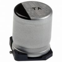
... F G 330 G Design, and specifications are each subject to change without notice. Ask factory for the current technical specifications before purchase and / or use. Should a safety concern arise regarding this product,please be sure to contact us immediately. Aluminum Electrolytic Capacitors/TA Country of Origin Japan < = -40 to +125 . 330 µ ...
Page 2
... EEVTA1A331P 118 0.32 EEVTA1C101P F 89 0.24 G EEVTA1C221P 113 0.24 EEVTA1E470P E 56 0.21 F EEVTA1E101P 84 0.21 EEVTA1V330P E 53 0.18 EEVTA1V470P F 79 0.18 G EEVTA1V101P 101 0.18 EEVTA1H100P E 25 0.18 E EEVTA1H220P 50 0.18 EEVTA1H330P F 74 0.18 G EEVTA1H470P 94 0.18 EE49 Min. Packaging (RoHS: Q'ty Taping (pcs) (2) 1000 ...
Page 3
... Pre-fix Suffix Case Diameter Compliant R 3mm to 5mm ECE-V P 6mm P 8mm to 10mm R 4mm to 5mm P 6mm P 8mm to 10mm EEV- Q 12.5mm M 16mm to 18mm R 3mm to 5mm EEE- P 6mm P 8mm to 10mm 260 250 240 230 220 210 200 Time in 200deg.C or more / s 260 250 240 230 220 ...