EEE-FK1H331AQ Panasonic - ECG, EEE-FK1H331AQ Datasheet
EEE-FK1H331AQ
Specifications of EEE-FK1H331AQ
EEEFK1H331AQ
PCE4849TR
Q3868273


Related parts for EEE-FK1H331AQ


EEE-FK1H331AQ Summary of contents
Page 1
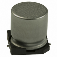
... V Design and specifi cations are each subject to change without notice. Ask factory for the current technical specifi cations before purchase and/or use. Should a safety concern arise regarding this product, please be sure to contact us immediately. Aluminum Electrolytic Capacitors/Medium-size FK V Type: – ...
Page 2
... EEEFK1E102AQ (9) EEEFK1E152AM (9) EEEFK1E222AM (9) EEEFK1E332AM (9) EEEFK1V471AQ (9) EEEFK1V681AQ (9) EEEFK1V102AM (9) EEEFK1V152AM (9) EEEFK1H331AQ (10) EEEFK1H391AQ (10) EEEFK1H471AM (10) EEEFK1H561AM (10) EEEFK1H681AM (10) EEEFK1H102AM (10) EEEFK1J151AQ (10) EEEFK1J221AQ (10) EEEFK1J471AM (10) EEEFK1J681AM (10) EEEFK1K680AQ (11) EEEFK1K101AQ (11) EEEFK1K151AQ (11) EEEFK1K331AM (11) EEEFK1K471AM (11) EEEFK2A470AQ (11) EEEFK2A680AQ (11) EEEFK2A101AM (11) EEEFK2A151AM (11) EEEFK2A221AM (11) EEEFK2A331AM (11) 00 200 125 200 125 125 200 125 125 200 125 125 ...