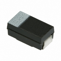
F911E106MCC Nichicon, F911E106MCC Datasheet - Page 7

F911E106MCC
Manufacturer Part Number
F911E106MCC
Description
CAP TANTALUM 10UF 25V 20% SMD
Manufacturer
Nichicon
Series
F91r
Type
Moldedr
Datasheet
1.F911D156MCC.pdf
(11 pages)
Specifications of F911E106MCC
Capacitance
10µF
Voltage - Rated
25V
Tolerance
±20%
Esr (equivalent Series Resistance)
450.0 mOhm
Operating Temperature
-55°C ~ 125°C
Mounting Type
Surface Mount
Package / Case
2312 (6032 Metric)
Size / Dimension
0.236" L x 0.126" W (6.00mm x 3.20mm)
Height
0.098" (2.50mm)
Manufacturer Size Code
C
Features
General Purpose
Voltage Rating
25 Volts
Esr
450 mOhms
Operating Temperature Range
- 55 C to + 125 C
Dimensions
3.2 mm W x 6 mm L
Mfr Case Code
C Case
Product
Tantalum Solid Low ESR Standard Grade
Termination Style
SMD/SMT
Lead Free Status / RoHS Status
Lead free / RoHS Compliant
Lead Spacing
-
Lead Free Status / Rohs Status
Details
Other names
493-2319-2
No.
11 Rapid change of temperature
12 Damp heat,steady state
13 Endurance
14 Characteristics at high and low temperature
Appearance
Leakage current
Capacitance change
Dissipation factor
Appearance
Leakage current
Capacitance change
Dissipation factor
Appearance
Leakage current
Capacitance change
Dissipation factor
Step2
Step4
Step5
125℃
Step6
-55℃
85℃
Capacitance
change
Dissipation factor
Leakage current
Capacitance
change
Dissipation factor
Leakage current
Capacitance
change
Dissipation factor
Leakage current
Capacitance
change
Dissipation factor
Item
No marked change
Not exceed the value shown
in No.3
Within ±5% of the value
before test
Not exceed the value shown
in No.5
No marked change
Not exceed the value shown
in No.3
Within ±10% of the value
before test
Not exceed the value shown
in No.5
No marked change
Not exceed the value shown
in No.3
Within ±10% of the value
before test
Not exceed the value shown
in No.5
Within +0/-10% of the value
in step1
Not exceed +2% of the value
shown in No.5
Not exceed 10 times of the
value shown in No.3
Within +10/-0% of the value
in step1
Not exceed the value shown
in No.5
Not exceed 12.5 times of the
value shown in No.3
Within +15/-0% of the
value in step1
Not exceed +2% of the value
shown in No.5
Not exceed the value shown
in No.3
Within ±3% of the value
in step1
Not exceed the value
shown in No.5
Performance characteristics
4.10
4.12 Test temp. : 40±2℃
4.15 ①
4.13
JIS C 5101-3
Number of cycles : 5cycles
Test hum.
Test time
②
StepTemp.(℃) Time(s)
Test temp. : 85±2℃
Test time
Applied V.
Source impedance
Test temp. : 125±3℃
Test time
Applied V.
Source impedance
Step
1
2
3
4
図番 DRAWING No.
1
2
3
4
5
6
Test method
125+3/-0
-55+0/-3
: 90∼95%R.H
: 500 +24/-0h
Temp.(℃)
R.T.
R.T.
125+3/-0
-55+0/-3
85+3/-0
TA20589
20±2
20±2
20±2
: 2000 +72/-0h
: 2000 +72/-0h
:
:
Rat.V
Derat.V
Point
:
:
Time
3 max
3 max
30±3
30±3
15 min
(TABLE-3)
3Ωmax.
3Ωmax.
2h
2h
頁 PAGE
6/9


