K104Z15Y5VE5TH5 Vishay, K104Z15Y5VE5TH5 Datasheet - Page 13
K104Z15Y5VE5TH5
Manufacturer Part Number
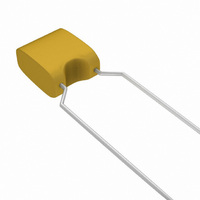
K104Z15Y5VE5TH5
Description
CAP .10UF 25V CERAMIC +80/-20%
Manufacturer
Vishay
Series
Mono-Kap™r
Specifications of K104Z15Y5VE5TH5
Capacitance
0.1µF
Voltage - Rated
25V
Tolerance
-20%, +80%
Temperature Coefficient
Y5V (F)
Mounting Type
Through Hole
Operating Temperature
-30°C ~ 85°C
Applications
General Purpose
Package / Case
Radial
Size / Dimension
0.157" L x 0.157" W (4.00mm x 4.00mm)
Thickness
2.50mm Max
Lead Spacing
0.200" (5.08mm)
Lead Style
Flat Bent
Voltage Rating
50 Volts
Termination Style
Radial
Operating Temperature Range
- 30 C to + 85 C
Product
Dipped MLCCs
Dimensions
4 mm W x 4 mm L x 4 mm H
Dielectric Characteristic
Y5V
Capacitance Tolerance
+80, -20%
Capacitor Case Style
Radial Leaded
No. Of Pins
2
Rohs Compliant
Yes
Lead Free Status / RoHS Status
Lead free / RoHS Compliant
Features
-
Ratings
-
Lead Free Status / Rohs Status
Lead free / RoHS Compliant
Other names
2252-362-10104
225236210104
BC1154TR
225236210104
BC1154TR


BCcomponents
ELECTRICAL CHARACTERISTICS
Table 4
The capacitors meet the essential requirements of “IEC 60384-8”, “IEC 60384-9” and “EIA 198”.
Unless stated otherwise all electrical values apply at an ambient temperature of 25 ± 3 ° C, at barometric pressures of
650 to 800 mm of mercury, and relative humidity not to exceed 75%.
2002 Oct 09
Capacitors with temperature coefficient NP0
Capacitance range:
Tolerance on the capacitance
Rated DC voltage
Dielectric strength
Insulation resistance at rated voltage
Temperature coefficient of the capacitance
Tolerance on the temperature coefficient
Dissipation factor:
Operating temperature range
Storage temperature range
Capacitors with temperature coefficient X7R
Capacitance range at 1 kHz, 1 V
Tolerance on the capacitance
Maximum capacitance variation
with respect to capacitance value at 25 ° C
Rated DC voltage
Dielectric strength
Insulation resistance at rated voltage
Dissipation factor at 1 kHz, 1 V
Operating temperature range
Storage temperature range
Ageing
Leaded ceramic multilayer
capacitors
at 1 MHz, 1 V; where C ≤ 1000 pF
at 1 kHz, 1 V; where C > 1000 pF
at 1 MHz, 1 V; where C ≤ 30 pF
at 1 kHz, 1 V; where C > 30 pF
Electrical data for NP0, X7R, Z5U and Y5V
DESCRIPTION
13
100000 M Ω or 1000 M Ω × µ F, whichever is less at rated
100000 M Ω or 1000 M Ω × µ F, whichever is less at rated
voltage within 2 minutes of charging
voltage within 2 minutes of charging
typical 1% per time decade
250% of rated voltage
250% of rated voltage
1200 pF to 5600 pF
100 pF to 0.22 µ F
<
− 55 to +125 ° C
− 55 to +125 ° C
10 to 1000 pF
50 and 100 V
------------------------------------- -
(
50 and 100 V
± 10%; ± 20%
± 30 × 10
Mono-kap
400
± 5%; ± 10%
< 15 × 10
0 × 10
25 ± 15 ° C
25 ± 15 ° C
VALUE
≤ 2.5%
± 15%
+
1
20
−6
−6
/K
×
−4
/K
C
)
Product specification
TM
series
Related parts for K104Z15Y5VE5TH5
Image
Part Number
Description
Manufacturer
Datasheet
Request
R

Part Number:
Description:
357-036-542-201 CARDEDGE 36POS DL .156 BLK LOPRO
Manufacturer:
Vishay
Datasheet:
Part Number:
Description:
357-036-542-201 CARDEDGE 36POS DL .156 BLK LOPRO
Manufacturer:
Vishay
Datasheet:
Part Number:
Description:
357-036-542-201 CARDEDGE 36POS DL .156 BLK LOPRO
Manufacturer:
Vishay
Datasheet:
Part Number:
Description:
357-036-542-201 CARDEDGE 36POS DL .156 BLK LOPRO
Manufacturer:
Vishay
Datasheet:
Part Number:
Description:
357-036-542-201 CARDEDGE 36POS DL .156 BLK LOPRO
Manufacturer:
Vishay
Datasheet:
Part Number:
Description:
357-036-542-201 CARDEDGE 36POS DL .156 BLK LOPRO
Manufacturer:
Vishay
Datasheet:
Part Number:
Description:
357-036-542-201 CARDEDGE 36POS DL .156 BLK LOPRO
Manufacturer:
Vishay
Datasheet:
Part Number:
Description:
357-036-542-201 CARDEDGE 36POS DL .156 BLK LOPRO
Manufacturer:
Vishay
Datasheet:
Part Number:
Description:
357-036-542-201 CARDEDGE 36POS DL .156 BLK LOPRO
Manufacturer:
Vishay
Datasheet:
Part Number:
Description:
357-036-542-201 CARDEDGE 36POS DL .156 BLK LOPRO
Manufacturer:
Vishay
Datasheet:
Part Number:
Description:
357-036-542-201 CARDEDGE 36POS DL .156 BLK LOPRO
Manufacturer:
Vishay
Datasheet:
Part Number:
Description:
357-036-542-201 CARDEDGE 36POS DL .156 BLK LOPRO
Manufacturer:
Vishay
Datasheet:
Part Number:
Description:
357-036-542-201 CARDEDGE 36POS DL .156 BLK LOPRO
Manufacturer:
Vishay
Datasheet:
Part Number:
Description:
357-036-542-201 CARDEDGE 36POS DL .156 BLK LOPRO
Manufacturer:
Vishay
Datasheet:
Part Number:
Description:
357-036-542-201 CARDEDGE 36POS DL .156 BLK LOPRO
Manufacturer:
Vishay
Datasheet: