C1608C0G2A101G TDK Corporation, C1608C0G2A101G Datasheet - Page 8
C1608C0G2A101G
Manufacturer Part Number
C1608C0G2A101G
Description
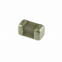
CAP CER 100PF 100V C0G 2% 0603
Manufacturer
TDK Corporation
Series
Cr
Datasheet
1.C1608C0G1H220G.pdf
(12 pages)
Specifications of C1608C0G2A101G
Capacitance
100pF
Voltage - Rated
100V
Tolerance
±2%
Temperature Coefficient
C0G, NP0
Mounting Type
Surface Mount, MLCC
Operating Temperature
-55°C ~ 125°C
Features
Low ESR
Applications
General Purpose
Package / Case
0603 (1608 Metric)
Size / Dimension
0.063" L x 0.031" W (1.60mm x 0.80mm)
Thickness
0.80mm
Lead Free Status / RoHS Status
Lead free / RoHS Compliant
Ratings
-
Lead Spacing
-
Other names
445-5380-2


* This series is available through the distribution channel only. Please see
• All specifications are subject to change without notice. Please read the precautions before using the product.
US Catalog // C Series — Tight Tolerance Capacitors // Version A11
No.
14
15
General
Specifications
Item
Moisture Resistance
External
appearance
Capacitance
Q (Class 1)
Insulation
Resistance
Life
External
appearance
Capacitance
Q (Class 1)
Insulation
Resistance
Performance
No mechanical damage.
500MΩ min.
No mechanical damage.
1,000MΩ min.
Rated Capacitance
C ≥ 30pF
10pF ≤ C < 30pF
C < 10pF
Characteristics
Class 1
Characteristics
Class 1
Rated Capacitance
C ≥ 30pF
C < 30pF
C0G
C0G
C : Rated capacitance (pF)
C : Rated capacitance (pF)
C Series — Tight Tolerance Capacitors
Change from the
value before test
Capacitance drift within
±3% or ±0.3pF,
whichever larger.
Change from the
value before test
Capacitance drift within
±7.5% or ±0.75pF,
whichever larger.
www.tdk.com/distributor.php
Q
350 min.
275 + 5/2×C min.
200 + 10×C min.
Q
200 min.
100 + 10/3×C min.
for a list of authorized distributors.
Test or Inspection Method
Reflow solder the capacitors on P.C. board (shown in
Appendix 1) before testing.
Apply the rated voltage at temperature 40±2ºC and 90
to 95%RH for 500 +24,0h.
Charge/discharge current shall not exceed 50mA.
Leave the capacitor in ambient conditions for 6 to 24h
before measurement.
Use this measurement for initial value.
Reflow solder the capacitor on P.C. board (shown in
Appendix 1) before testing.
Apply 2x rated voltage at 125±2ºC for 1,000 +48, 0h.
Charge/discharge current shall not exceed 50mA.
Leave the capacitors in ambient condition for 6 to 24h
before measurement.
Use this measurement for initial value.
Related parts for C1608C0G2A101G
Image
Part Number
Description
Manufacturer
Datasheet
Request
R

Part Number:
Description:
TDK DC to DC Converters, DC to AC Inverters
Manufacturer:
TDK Corporation
Datasheet:
Part Number:
Description:
TDK DC to DC Converters, DC to AC Inverters
Manufacturer:
TDK Corporation
Datasheet: