T197A156K015AS Kemet, T197A156K015AS Datasheet - Page 9
T197A156K015AS
Manufacturer Part Number
T197A156K015AS
Description
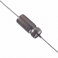
CAP TANT-WET 15UF 15V 10% AXIAL
Manufacturer
Kemet
Series
T197r
Type
Hermetically Sealedr
Datasheet
1.T197A566K008AS.pdf
(28 pages)
Specifications of T197A156K015AS
Capacitance
15µF
Voltage - Rated
15V
Tolerance
±10%
Esr (equivalent Series Resistance)
4.420 Ohm
Operating Temperature
-55°C ~ 200°C
Mounting Type
Through Hole
Package / Case
Axial
Size / Dimension
0.219" Dia x 0.453" L (5.56mm x 11.51mm)
Manufacturer Size Code
A
Features
Wet Tantalum
Lead Free Status / RoHS Status
Contains lead / RoHS non-compliant
Height
-
Lead Spacing
-
Other names
399-3406
T197A156K015AS7340
T197A156K015AS7340


•
Step 3, +25°C
Step 4, +85°C
Step 5, +125°C DCL shall not exceed 12.5
Step 6, +25°C
Note: MIL-PRF-39006 specifies Δ’s and limits by
individual slash sheet.
AC Ripple Life at 85°C: Per MIL-STD-202,
Method 108:
The following details shall apply:
a. Distance of temperature measurements
from specimens : Not applicable
DCL as indicated in original
limit; capacitance within ±5%
of initial value; ESR, DF within
limit ±5% of inital value; ESR,
DF within limit shown in Part
Number Tables.
DCL shall not exceed 10 times
original DCL limit at 25°C.
Capacitance shall be within
±10% of the initial value. DF
shall be within 125% of limits
shown in Part Number Tables.
ESR shall be within limits shown
in Part Number Tables.
times the original limit at 25°C.
Capacitance shall be within
±12% of initial value. DF shall be
within 150% of limits shown in
Part Number Tables. ESR shall
be within limits shown in Part
Number Tables.
DCL as indicated in original
limit; capacitance within ±5% of
initial value; ESR, DF as i n d i -
cated in original limit shown in
Part Number Tables.
© KEMET Electronics Corporation, P.O. Box 5928, Greenville, SC 29606 (864) 963-6300
Figure 7. Optimum Solder Wave Profile
18. High Temperature Capacitors - T197
+85°C, as with all other tantalum capacitors. There will
be a linear derating between 100% at +85°C and 2/3
(67%) at +125°C. For the 200°C rated parts, the volt-
age rating shall be 50%.
all temperatures up to +85°C. From +85°C to +125°C,
the reverse voltage rating shall be 2 VDC. From
+125°C to +200°C, the reverse voltage rating shall be
1.0 VDC.
19. Mounting
Soldering Heat Test of MIL-STD-202, Method 210,
Condition C. This test simulates wave solder of topside
board mount product. This demonstration of resistance
to solder heat is in accordance with what is believed to be
the industry standard. More severe treatment must be
considered reflective of an improper soldering process.
profile for wet tantalum capacitors
•
and T198 Series
The voltage derating for these capacitors begins at
For reverse voltage rating, the 3 VDC shall apply to
Wet tantalum capacitors will pass the Resistance to
Shown in Figure 7 is a recommended solder wave
b. Method of mounting: Normal means
c. Test condition letter: F (2000 hours, +72 hrs, -
d. DC Leakage, DF shall not exceed initial limit
Seal Condition: Per MIL-STD-202,
Method 112
Conditions A or D, and C
Ohm)
Performance Characteristics
9
Related parts for T197A156K015AS
Image
Part Number
Description
Manufacturer
Datasheet
Request
R

Part Number:
Description:
CAP, KEMET #F601BL105K250C
Manufacturer:
Kemet
Datasheet:
Part Number:
Description:
Manufacturer:
Kemet
Datasheet:
Part Number:
Description:
Manufacturer:
Kemet
Datasheet: