CLLC1AX7S0G474M TDK Corporation, CLLC1AX7S0G474M Datasheet - Page 8
CLLC1AX7S0G474M
Manufacturer Part Number
CLLC1AX7S0G474M
Description
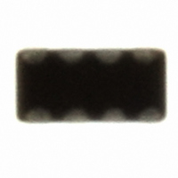
CAP LOW ESL .47UF 4V X7S 0603
Manufacturer
TDK Corporation
Series
CLLr
Datasheet
1.CLLE1AX7R1A104M.pdf
(13 pages)
Specifications of CLLC1AX7S0G474M
Capacitance
0.47µF
Voltage - Rated
4V
Tolerance
±20%
Temperature Coefficient
X7S
Mounting Type
Surface Mount, MLCC
Operating Temperature
-55°C ~ 125°C
Features
Low ESL, Multi-Terminal
Applications
General Purpose
Package / Case
0603 (1608 Metric)
Size / Dimension
0.063" L x 0.031" W (1.60mm x 0.80mm)
Thickness
0.55mm Max
Lead Free Status / RoHS Status
Lead free / RoHS Compliant
Ratings
-
Lead Spacing
-
Other names
445-3392-2


• All specifications are subject to change without notice. Please read the precautions before using the product.
US Catalog // CLL Series — Ultra Low Inductance Capacitors // Version A11
No.
12
13
14
General
Specifications
Item
Moisture Resistance (Steady State)
External
appearance
Capacitance
D.F. (Class 2)
Insulation
Resistance
Moisture Resistance
External
appearance
Capacitance
D.F. (Class 2)
Insulation
Resistance
Life
External
appearance
Capacitance
D.F. (Class 2)
Insulation
Resistance
CLL Series — Ultra Low Inductance Capacitors
Performance
No mechanical damage.
Characteristics:
X7R: 200% of initial spec. max.
X7S: 200% of initial spec. max.
10MΩ·μF min.
No mechanical damage.
Characteristics
X7R: 200% of initial spec. max.
X7S: 200% of initial spec. max.
5MΩ·μF min.
No mechanical damage.
Characteristics
X7R: 200% of initial spec. max.
X7S: 200% of initial spec. max.
10MΩ·μF min.
Characteristics
Characteristics
Characteristics
X7R
X7S
X7R
X7S
X7R
X7S
Change from the
value before test
± 12.5 %
Change from the
value before test
± 12.5 %
Change from the
value before test
± 15 %
Test or Inspection Method
Reflow solder the capacitor on P.C. board (shown in
Appendix 1 and 2) before testing.
Leave at temperature 40±2ºC and 90 to 95%RH for
500 +24,0h.
Leave the capacitor in ambient condition for 24±2h
before measurement.
Reflow solder the capacitors on P.C. board (shown in
Appendix 1 and 2) before testing.
Apply the rated voltage at temperature 40±2ºC and 90
to 95%RH for 500 +24,0h.
Charge/discharge current shall not exceed 50mA.
Leave the capacitor in ambient conditions for 48±4h
before measurement.
Voltage conditioning:
Voltage treat the capacitors under testing temperature
and voltage for 1 hour.
Leave the capacitors in ambient condition for 24±2h
before measurement.
Use this measurement for initial value.
Reflow solder the capacitor on P.C. board (shown in
Appendix 1 and 2) before testing.
Apply 1 x rated voltage at 125±2ºC for 1,000 +48, 0h.
Charge/discharge current shall not exceed 50mA.
Leave the capacitors in ambient condition for 24±2h
before measurement.
Voltage conditioning:
Voltage treat the capacitor under testing temperature
and voltage for 1 hour.
Leave the capacitor in ambient conditions for 48±4h
before measurement.
Use this measurement for initial value.
Related parts for CLLC1AX7S0G474M
Image
Part Number
Description
Manufacturer
Datasheet
Request
R

Part Number:
Description:
TDK DC to DC Converters, DC to AC Inverters
Manufacturer:
TDK Corporation
Datasheet:
Part Number:
Description:
TDK DC to DC Converters, DC to AC Inverters
Manufacturer:
TDK Corporation
Datasheet: