GRM21BR71A106KE51L Murata Electronics North America, GRM21BR71A106KE51L Datasheet - Page 2
GRM21BR71A106KE51L
Manufacturer Part Number
GRM21BR71A106KE51L
Description
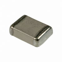
CAP CER 10UF 10V X7R 0805
Manufacturer
Murata Electronics North America
Series
GRMr
Datasheets
1.GNM1M2R71E472MA01D.pdf
(4 pages)
2.GRM033R60J104KE19D.pdf
(3 pages)
3.GRM21BR71A106KE51L.pdf
(1 pages)
Specifications of GRM21BR71A106KE51L
Capacitance
10µF
Voltage - Rated
10V
Tolerance
±10%
Temperature Coefficient
X7R
Mounting Type
Surface Mount, MLCC
Operating Temperature
-55°C ~ 125°C
Applications
General Purpose
Package / Case
0805 (2012 Metric)
Size / Dimension
0.079" L x 0.049" W (2.00mm x 1.25mm)
Thickness
1.25mm
Lead Free Status / RoHS Status
Lead free / RoHS Compliant
Features
-
Ratings
-
Lead Spacing
-
Other names
490-3905-2
Available stocks
Company
Part Number
Manufacturer
Quantity
Price
Company:

Part Number:
GRM21BR71A106KE51L
Manufacturer:
MURATA
Quantity:
640 000
Company:
Part Number:
GRM21BR71A106KE51L
Manufacturer:
MURATA
Quantity:
3 000
Part Number:
GRM21BR71A106KE51L
Manufacturer:
MURATA/村田
Quantity:
20 000


!Note
No.
10
11 Vibration
12 Deflection
13
*2: GRM31CR60J107, GRM31CD80G107: 0.15 max.
*3: GRM31CR71E106: 0.125 max.
GRM Series Specifications and Test Methods (2)
Continued from the preceding page.
Adhesive Strength
of Termination
Solderability of
Termination
1. This Specifications and Test Methods is downloaded from the website of Murata Manufacturing co.,ltd. Therefore, it's specifications are subject to change or our products in it may be discontinued without advance notice.
0.
2. This Specifications and Test Methods has only typical specifications because there is no space for detailed specifications. Therefore, please approve our product specifications or transact the approval sheet for product
0.
Please check with our sales representatives or product engineers before ordering.
specifications before ordering.
Item
Appearance
Capacitance
D.F.
Appearance
Capacitance
Change
No removal of the terminations or other defects should occur.
No defects or abnormalities
Within the specified tolerance
B1, B3, R1, R6*
C6: 0.125 max.
F1, F5: 0.2 max.
No marking defects
Within 10%
75% of the terminations is to be soldered evenly and
continuously.
2
, R7*
R230
3
Capacitance meter
45
, C7, C8, E7, D7, D8*
Specifications
20
Fig. 1a
Fig.3a
50
Pressurize
45
Pressurizing
speed : 1.0mm/sec.
c
Flexure : V1
Solder resist
Baked electrode or
copper foil
2
: 0.1 max.
Solder the capacitor on the test jig (glass epoxy board) shown
in Fig. 1a using an eutectic solder. Then apply 10N* force in
parallel with the test jig for 10 1sec.
The soldering should be done either with an iron or using the
reflow method and should be conducted with care so that the
soldering is uniform and free of defects such as heat shock.
*1N: GRM02, 2N: GRM03, 5N: GRM15/GRM18
Solder the capacitor on the test jig (glass epoxy board) in the
same manner and under the same conditions as (10).
The capacitor should be subjected to a simple harmonic motion
having a total amplitude of 1.5mm, the frequency being varied
uniformly between the approximate limits of 10 and 55Hz. The
frequency range, from 10 to 55Hz and return to 10Hz, should
be traversed in approximately 1 minute. This motion should be
applied for a period of 2 hours in each of 3 mutually
perpendicular directions (total of 6 hours).
Solder the capacitor on the test jig (glass epoxy board) shown
in Fig. 2a using an eutectic solder. Then apply a force in the
direction shown in Fig. 3a for 5 1 sec. The soldering should be
done by the reflow method and should be conducted with care
so that the soldering is uniform and free of defects such as heat
shock.
Immerse the capacitor in a solution of ethanol (JIS-K-8101) and
rosin (JIS-K-5902) (25% rosin in weight proportion) .
Preheat at 80 to 120 C for 10 to 30 seconds.
After preheating, immerse in an eutectic solder solution for
2 0.5 seconds at 230 5 C or Sn-3.0Ag-0.5Cu solder solution
for 2 0.5 seconds at 245 5 C.
GRM02
GRM03
GRM15
GRM18
GRM21
GRM31
GRM32
GRM43
GRM55
GRM02
GRM03
GRM15
GRM18
GRM21
GRM31
GRM32
GRM43
GRM55
Type
Type
0.2
0.3
0.4
1.0
1.2
2.2
2.2
3.5
4.5
0.2
0.3
0.4
1.0
1.2
2.2
2.2
3.5
4.5
Test Method
a
a
Fig. 2a
100
Continued on the following page.
b
c
a
0.56
0.56
0.9
1.5
3.0
4.0
5.0
5.0
7.0
8.0
0.9
1.5
3.0
4.0
5.0
5.0
7.0
8.0
b
b
ø4.5
(GRM02/03/15: t: 0.8mm)
0.23
1.65
0.23
1.65
0.3
0.5
1.2
2.0
2.9
3.7
5.6
0.3
0.5
1.2
2.0
2.9
3.7
5.6
c
c
(in mm)
t: 1.6mm
Related parts for GRM21BR71A106KE51L
Image
Part Number
Description
Manufacturer
Datasheet
Request
R

Part Number:
Description:
BUZZER PIEZO 25VP-P SMD
Manufacturer:
Murata Electronics North America

Part Number:
Description:
CAP 4-ARRAY 680PF 100V X7R 1206
Manufacturer:
Murata Electronics North America
Datasheet:
Part Number:
Description:
CAP 4-ARRAY 1000PF 100V X7R 1206
Manufacturer:
Murata Electronics North America
Datasheet:
Part Number:
Description:
CAP 4-ARRAY 1800PF 100V X7R 1206
Manufacturer:
Murata Electronics North America
Datasheet:
Part Number:
Description:
CAP 4-ARRAY 68000PF 16V X7R 1206
Manufacturer:
Murata Electronics North America
Datasheet:

Part Number:
Description:
CAP CER 1000PF 50V 10% X7R 0402
Manufacturer:
Murata Electronics North America
Datasheet:
Part Number:
Description:
CAP CER 10000PF 16V 10% X7R 0402
Manufacturer:
Murata Electronics North America
Datasheet:

Part Number:
Description:
CAP 5.5-25PF 2.5X3.2MM SMD
Manufacturer:
Murata Electronics North America
Datasheet:

Part Number:
Description:
CAP 4.5-20PF 2.5X3.2MM SMD
Manufacturer:
Murata Electronics North America
Datasheet:

Part Number:
Description:
CAP 5.0-20PF 3.2X4.5MM SMD RED
Manufacturer:
Murata Electronics North America
Datasheet:

Part Number:
Description:
CAP 2.0-6.0PF 3.2X4.5MM SMD BLU
Manufacturer:
Murata Electronics North America
Datasheet:

Part Number:
Description:
CAP 1.4-3.0PF 3.2X4.5MM SMD BRN
Manufacturer:
Murata Electronics North America
Datasheet:

Part Number:
Description:
CAP 3.0-10PF 3.2X4.5MM SMD WHT
Manufacturer:
Murata Electronics North America
Datasheet:

Part Number:
Description:
CAP 2.0-6.0PF 4X4.5MM TOPADJ BLU
Manufacturer:
Murata Electronics North America
Datasheet:

Part Number:
Description:
CAP 8.5-40PF 4X4.5MM TOPADJ YEL
Manufacturer:
Murata Electronics North America
Datasheet: