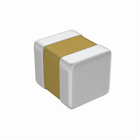
05045C103KA19A AVX Corporation, 05045C103KA19A Datasheet - Page 10

05045C103KA19A
Manufacturer Part Number
05045C103KA19A
Description
CAP CER 10000PF 50V X7R 0504
Manufacturer
AVX Corporation
Datasheet
1.05041A1R0DAT1A.pdf
(48 pages)
Specifications of 05045C103KA19A
Capacitance
10000pF
Voltage - Rated
50V
Tolerance
±10%
Temperature Coefficient
X7R
Mounting Type
Surface Mount, MLCC
Operating Temperature
-55°C ~ 125°C
Features
Low ESL
Applications
General Purpose
Package / Case
0504 (1210 Metric)
Size / Dimension
0.050" L x 0.040" W (1.27mm x 1.02mm)
Thickness
1.02mm Max
Lead Free Status / RoHS Status
Lead free / RoHS Compliant
Ratings
-
Lead Spacing
-
C0G (NP0) Dielectric
General Specifications
PART NUMBER (see page 7 for complete information and options)
PERFORMANCE CHARACTERISTICS
8
Capacitance Range
Capacitance Tolerances
Operating Temperature Range
Temperature Characteristic
Voltage Ratings
Dissipation Factor and “Q”
Insulation Resistance (+25°C, RVDC)
Insulation Resistance (+125°C, RVDC)
Dielectric Strength
Test Voltage
Test Frequency
(L" x W")
0805
Size
100V = 1
200V = 2
Voltage
25V = 3
50V = 5
5
C0G (NP0) = A
Dielectric
A
Capacitance
101
Code
0.5 pF to .068 µF (1.0 ±0.2 Vrms, 1kHz, for ≤100 pF use 1 MHz)
Preferred ±5%, ±10%
others available: ±.25 pF, ±.5 pF, ±1% (≥25pF), ±2%(≥13pF), ±20%
For values ≤ 10 pF preferred tolerance is ±.5 pF, also available ±.25 pF.
-55°C to +125°C
0 ± 30 ppm/°C (EIA C0G)
25, 50, 100 & 200 VDC (+125°C)
For values >30 pF: 0.1% max. (+25°C and +125°C)
For values ≤30 pF: “Q” = 400 + 20 x C (C in pF)
100,000 megohms min. or 1000 MΩ - µF min., whichever is less
10,000 megohms min. or 100 MΩ - µF min., whichever is less
250% of rated voltage for 5 seconds at 50 mamp max. current
1 ± 0.2 Vrms
For values ≤100 pF: 1 MHz
For values >100 pF: 1 KHz
Capacitance
Tolerance
K = ±10%
J = ± 5%
Preferred
J
ature-compensating,” EIA Class I ceramic materials. Modern
NP0 formulations contain neodymium, samarium and other
rare earth oxides.
dielectrics available. Capacitance change with temperature is
0 ±30ppm/°C which is less than ±0.3% ∆ C from -55°C to
+125°C. Capacitance drift or hysteresis for NP0 ceramics is
negligible at less than ±0.05% versus up to ±2% for films.
Typical capacitance change with life is less than ±0.1% for
NP0s, one-fifth that shown by most other dielectrics. NP0
formulations show no aging characteristics.
and shows little capacitance or “Q” changes with frequency.
Their dielectric absorption is typically less than 0.6% which is
similar to mica and most films.
C0G (NP0) is the most popular formulation of the “temper-
NP0 ceramics offer one of the most stable capacitor
The NP0 formulation usually has a “Q” in excess of 1000
Applicable
Failure
A = Not
Rate
A
Terminations
T = Plated Ni
and Solder
T
Paper/Unmarked
Packaging
2 = 7" Reel
2
Special
A = Std.
Product
Code
A


