DE2F3KH103MA3B Murata Electronics North America, DE2F3KH103MA3B Datasheet - Page 45
DE2F3KH103MA3B
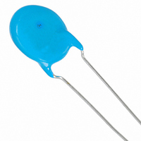
Manufacturer Part Number
DE2F3KH103MA3B
Description
CAP 10000PF 250VAC F X1Y2 RAD
Manufacturer
Murata Electronics North America
Series
KHr
Datasheets
1.DEBB33A681KA2B.pdf
(72 pages)
2.DE2B3KY221KA2BM01.pdf
(1 pages)
3.DE2B3KY221KA2BM01.pdf
(4 pages)
Specifications of DE2F3KH103MA3B
Capacitance
10000pF
Voltage - Rated
250VAC
Tolerance
±20%
Temperature Coefficient
F
Mounting Type
Through Hole
Operating Temperature
-25°C ~ 85°C
Applications
Safety
Ratings
X1Y2
Package / Case
Radial - Disc
Size / Dimension
0.630" Dia (16mm)
Thickness
7.00mm Max
Lead Spacing
0.295" (7.50mm)
Lead Style
Straight
Lead Free Status / RoHS Status
Lead free / RoHS Compliant
Features
-
Other names
490-4217


!Note
• This PDF catalog is downloaded from the website of Murata Manufacturing co., ltd. Therefore, it’s specifications are subject to change or our products in it may be discontinued without advance notice. Please check with our
• This PDF catalog has only typical specifications because there is no space for detailed specifications. Therefore, please approve our product specifications or transact the approval sheet for product specifications before ordering.
sales representatives or product engineers before ordering.
!Note
No.
13
15
16
14
17 Life
*
*
1
2
"room condition" Temperature: 15 to 35°C, Relative humidity: 45 to 75%, Atmospheric pressure: 86 to 106kPa
"C" expresses nominal capacitance value (pF).
Continued from the preceding page.
Soldering Effect
(On-Preheat)
Temperature
Cycle
Humidity (Under
Steady State)
Humidity
Loading
• Please read rating and !CAUTION (for storage, operating, rating, soldering, mounting and handling) in this catalog to prevent smoking and/or burning, etc.
• This catalog has only typical specifications because there is no space for detailed specifications. Therefore, please approve our product specifications or transact the approval sheet for product specifications before ordering.
Item
Appearance
Capacitance
Change
Dielectric Strength
(Between Lead
Wires)
Appearance
Capacitance
Change
Q
I.R.
Dielectric Strength
(Between Lead
Wires)
Appearance
Capacitance
Change
Q
I.R.
Appearance
Capacitance
Change
Q
I.R.
Appearance
Capacitance
Change
Q
I.R.
No marked defect
Within ±2.5%
Per item 4.
No marked defect
Within ±5%
275+5/2C*
350 min. (30pF min.)
1000MΩ min.
Per item 4.
No marked defect
Within ±5%
275+5/2C*
350 min. (30pF min.)
1000MΩ min.
No marked defect
Within ±5%
275+5/2C*
350 min. (30pF min.)
1000MΩ min.
No marked defect
Within ±3%
275+5/2C*
350 min. (30pF min.)
2000MΩ min.
2
2
2
2
min. (30pF under)
min. (30pF under)
min. (30pF under)
min. (30pF under)
Specifications
DEA Series Specifications and Test Methods
First the capacitor should be
stored at 120+0/-5°C for
60+0/-5 sec.
Then, as in figure, the lead wires
should be immersed in solder of
260+0/-5°C up to 1.5 to 2.0mm
from the root of terminal for
7.5+0/-1 sec.
Post-treatment:
The capacitor should be subjected to 5 temperature cycles.
<Temperature Cycle>
Post-treatment:
Set the capacitor for 500+24/-0 hrs. at 40±2°C in 90 to 95%
relative humidity.
Post-treatment:
Apply the rated voltage for 500+24/-0 hrs. at 40±2°C in 90 to
95% relative humidity.
(Charge/Discharge currentV50mA)
Post-treatment:
Apply a DC voltage of 150% of the rated voltage for
1000+48/-0 hrs. at 125±2°C with a relative humidity of 50%
max. (Charge/Discharge currentV50mA)
Post-treatment:
Capacitor should be stored for 1 to 2 hrs. at room condition*
Capacitor should be stored for 1 to 2 hrs. at room condition*
Capacitor should be stored for 1 to 2 hrs. at room condition*
Capacitor should be stored for 1 to 2 hrs. at room condition*
Capacitor should be stored for 1 to 2 hrs. at room condition*
Step
1
2
3
4
Temperature (°C)
Test Method
Room Temp.
Room Temp.
125±3
-25±3
Cycle time: 5 cycle
Thermal
Screen
Time (min)
30
30
3
3
Capacitor
Molten
Solder
1.5
to 2.0mm
C85E.pdf
1
1
1
1
1
43
.
.
.
.
.
08.10.29
8
Related parts for DE2F3KH103MA3B
Image
Part Number
Description
Manufacturer
Datasheet
Request
R

Part Number:
Description:
BUZZER PIEZO 25VP-P SMD
Manufacturer:
Murata Electronics North America

Part Number:
Description:
CAP 4-ARRAY 680PF 100V X7R 1206
Manufacturer:
Murata Electronics North America
Datasheet:
Part Number:
Description:
CAP 4-ARRAY 1000PF 100V X7R 1206
Manufacturer:
Murata Electronics North America
Datasheet:
Part Number:
Description:
CAP 4-ARRAY 1800PF 100V X7R 1206
Manufacturer:
Murata Electronics North America
Datasheet:
Part Number:
Description:
CAP 4-ARRAY 68000PF 16V X7R 1206
Manufacturer:
Murata Electronics North America
Datasheet:

Part Number:
Description:
CAP CER 1000PF 50V 10% X7R 0402
Manufacturer:
Murata Electronics North America
Datasheet:
Part Number:
Description:
CAP CER 10000PF 16V 10% X7R 0402
Manufacturer:
Murata Electronics North America
Datasheet:

Part Number:
Description:
CAP 5.5-25PF 2.5X3.2MM SMD
Manufacturer:
Murata Electronics North America
Datasheet:

Part Number:
Description:
CAP 4.5-20PF 2.5X3.2MM SMD
Manufacturer:
Murata Electronics North America
Datasheet:

Part Number:
Description:
CAP 5.0-20PF 3.2X4.5MM SMD RED
Manufacturer:
Murata Electronics North America
Datasheet:

Part Number:
Description:
CAP 2.0-6.0PF 3.2X4.5MM SMD BLU
Manufacturer:
Murata Electronics North America
Datasheet:

Part Number:
Description:
CAP 1.4-3.0PF 3.2X4.5MM SMD BRN
Manufacturer:
Murata Electronics North America
Datasheet:

Part Number:
Description:
CAP 3.0-10PF 3.2X4.5MM SMD WHT
Manufacturer:
Murata Electronics North America
Datasheet:

Part Number:
Description:
CAP 2.0-6.0PF 4X4.5MM TOPADJ BLU
Manufacturer:
Murata Electronics North America
Datasheet:

Part Number:
Description:
CAP 8.5-40PF 4X4.5MM TOPADJ YEL
Manufacturer:
Murata Electronics North America
Datasheet: