IR21593 International Rectifier, IR21593 Datasheet
IR21593
Specifications of IR21593
Available stocks


Related parts for IR21593

IR21593 Summary of contents
Page 1
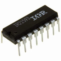
... The heart of this control voltage- controlled oscillator with externally programmable minimum frequency. The IR21592/ IR21593 are available in both 16 pin DIP and 16 pin narrow body SOIC packages. Typical Connection + Rectified AC Line + DC Bus 0 ...
Page 2
... IR21592/IR21593 Absolute Maximum Ratings Absolute maximum ratings indicate sustained limits beyond which damage to the device may occur. All voltage parameters are absolute voltages referenced to COM, all currents are defined positive into any lead. The thermal resistance and power dissipation ratings are measured under board mounted and still air conditions. ...
Page 3
... UVLO mode quiescent current QCCUV I Fault-mode quiescent current QCCFLT I V supply current @ FMIN (IR21592) CCFMIN supply current @ FMAX (IR21592) CCFMAX supply current @ FMIN (IR21593) CCFMIN supply current @ FMAX (IR21593) CCFMAX zener shunt clamp voltage CLAMP CC www.irf.com IR21592/IR21593 voltage for proper HO functionality . ...
Page 4
... Amplitude control VCO pin charging current I VCOPK t LO output deadtime (IR21592) DTLO t HO output deadtime (IR21592) DTHO t LO output deadtime (IR21593) DTLO t HO output deadtime (IR21593) DTHO Gate Driver Output Characteristics tr Turn-on rise time tf Turn-off fall time & ( PbF ) = 0.5V 0.0V 40k ...
Page 5
... DIM minimum reference voltage (MIN pin) MINMIN V DIM maximum reference voltage (MIN pin) MINMAX Minimum Frequency Setting V FMIN pin voltage during normal operation FMIN V FMIN pin voltage during fault mode FMINFLT www.irf.com IR21592/IR21593 = 0.5V 0.0V 40k FMIN VCO unless otherwise specified. A Min. Typ. ...
Page 6
... IR21592/IR21593 Block Diagram VCC 60uA VCO 2 15uA 1uA VDC 1 1.0uA CPH 3 REF 10V S Q DIM 4 5. DIM FB MAX 5 0.1/R 4/R FMIN FMIN MIN 6 0.1/R FMIN DIM I FMIN 1/R FMIN 7 FMIN 5.1V 5.1V 1 1.6V IPH 8 0 Lead Assignments & Definitions Pin Assignments ...
Page 7
... Strike Lamp or Hard Switching > 165C J (Over-Temperature) CS > V (1.6V) CSTH (Over-Current or Hard Switching > 165C V >V (Over-Temperature www.irf.com IR21592/IR21593 Power Turned On UVLO Mode 1/2-Bridge Off IQCC=200mA CPH=0V Oscillator Off VCC > 12.5V (UV+) and VDC > 5.1V (Bus OK) and SD < 1.7V and T < 165C J PREHEAT Mode 1/2-BridgeOscillator On ...
Page 8
... IR21592/IR21593 Timing Diagram Non-strike fault condition with lamp exchange VCC 15.6V UVLO+ UVLO- VDC VDCTH+ VDCTH- CPH 5.1V V DIM VCO 1.6V V IPH UVLO & ( PbF ) FLT DIM UVLO www.irf.com ...
Page 9
... DIM MIN be set after R . FMIN R sets the upper phase boundary MAX corresponding to maximum lamp power when volts. R must be set DIM MAX after R and R . FMIN MIN www.irf.com IR21592/IR21593 BEGIN Calculate R PULL-UP VAC = − R TURN ON PULL − QCCUV Calculate R VDC ...
Page 10
... FMIN Graph (IR21592/IR21593) MIN FMIN & ( PbF ) 200 160 =5V 120 = Graph 2. Frequency vs R (IR21592) 110 100 Graph =5V VCO V =2V VCO V =0V VCO RFMIN (K ) (IR21593) FMIN FMIN vs R (IR21592/IR21593) IPH FMIN www.irf.com 70 70 ...
Page 11
... V (V) MIN Graph MIN 3 2.5 2 1.5 1 0 Temperature °C Graph Temperature (IR21592/IR21593) CPH www.irf.com IR21592/IR21593 2. (IR21592/IR21593) 150 140 130 120 110 100 90 -25 75 100 125 Graph & ( PbF ) 2.2 2.4 2.6 2.8 V (V) MIN Graph 6 ...
Page 12
... Graph 11. Frequency vs Temperature (IR21592) RFMIN=39K & ( PbF ) 6 5.6 5.2 4.8 4 100 125 -25 160 V VCO 120 V VCO 80 V VCO 40 0 -25 75 100 125 Graph 12. Frequency vs Temperature (IR21593 100 Temperature °C Graph 10 Temperature FMIN (IR21592/IR21593) =5V =3V = 100 Temperature °C RFMIN=39K www.irf.com 125 125 ...
Page 13
... Temperature °C Graph 15. TDEAD vs Temperature (IR21592) www.irf.com IR21592/IR21593 6 5.6 5.2 4.8 4 100 125 -25 Graph 14 1.6 1.2 0.8 0 100 125 -25 Graph 16. TDEAD vs Temperature (IR21593 & ( PbF ) 100 125 Temperature °C vs Temperature (IR21592/ FMIN IR21593 100 125 Temperature °C 13 ...
Page 14
... IR21592/IR21593 Functional Description Phase Control To understand phase control, a simplified model for the ballast output stage is used (Figure 1). The lamp and filaments are replaced with resistors, with the lamp inserted between the filament resistors (R1, R2, R3 and R4 Rlamp Vin R3 Figure 1, Dimming ballast output stage. ...
Page 15
... IC is fully functional before the high and low side output drivers are activated. Figure 5 shows an efficient supply voltage using the start-up current of the IR21592/IR21593 together with a charge pump from the ballast output stage (R1, C1, C2, D1 and D2). V ...
Page 16
... VCC exceeds the UVLO+ threshold and VDC exceeds 5.1V. HO and LO begin to oscillate at the maximum operating frequency with 50% duty cycle and at the internally set dead-time of 2us (IR21592 (IR21593). Pin CPH is disconnected from COM and an internal 1uA current source (Figure 7) charges the external timing capacitor on CPH linearly. ...
Page 17
... IR21592/IR21593 is reached. If the current limit is reached, the IR21592/IR21593 enters FAULT mode. The 1.6V threshold together with the external current ...
Page 18
... VIPH Pre-Heat +10% when the lamp ignites. Ignition-to-Dim (IGN-to-DIM) When the IR21592/IR21593 enters dim mode, the phase control loop is closed and the phase of the & ( PbF ) load current is regulated against the user control input on pin DIM ...
Page 19
... CONTROL R MIN V (-) BUS Figure 12, IR21592/IR21593 dimming circuitry. Once lock is achieved, the phase detector (PDET) outputs short pulses to an open-drain PMOS that charges the VCO capacitor through an internal resistor (RFB) each time an error pulse occurs (Figure 13). This action "nudges" the integrator at the input of the VCO to keep the phase of the output stage current exactly locked in phase with the reference ...
Page 20
... IR21592/IR21593 V MIN MIN R MAX USER 0.5V 5V SETTING V DIM LO REF 0 Figure 14, Dimming interface The charging time of CT from 1V to 5.1V determines the on-time of output gate drivers HO and LO and corresponds to -180 degrees of possible phase shift in load current (minus deadtime). For the 0 to -90 degree dim range, the voltage on pin MIN is bounded between 1V and 3V using pins MIN and MAX ...
Page 21
... HO and LO, are both turned off. Cycling the supply voltage on VCC below UVLO the voltage on pin SD above and below SD+ and SD- will reset the IR21592/IR21593 to preheat (PH) mode (see STATE DIAGRAM). Ballast Design Lamp Requirements Before selecting component values for the ballast ...
Page 22
... I ign I Cath 1 % Table II, Ballast design constraints IR21592/IR21593 Programmable Inputs [Hz] (4) In order to program the MIN and MAX settings of the dimming interface, the phase of the output stage current at minimum and maximum lamp power must be calculated. This is obtained using the following equations: [App] (5) ...
Page 23
... With the lamp requirements defined, the L and C of the ballast output stage selected, and the minimum and maximum phase calculated, the component values for setting the programmable inputs of the IR21592/IR21593 are obtained with the following equations 10000 R MIN FMIN ( f 10000 ) MIN 2 ...
Page 24
... IR21592/IR21593 This ballast design procedure has been summarized into the following 3 steps: Figure 19, Simplified Ballast Design Procedure & ( PbF ) Define Lamp Requirements Iterate L and C to fulfill constraints Calculate IR21592/IR21593 IR2159 Programmable Inputs www.irf.com ...
Page 25
... Case outline www.irf.com IR21592/IR21593 16 Lead PDIP 16 -Lead SOIC (narrow body & ( PbF ) 01-6015 01-3065 00 (MS-001A) 01-6018 01-3064 00 (MS-012AC) 25 ...
Page 26
... SPN code) Assembly site code ORDER INFORMATION Leadfree Part 16-Lead PDIP IR21592 order IR21592PbF 16-Lead SOIC IR21592S order IR21592SPbF 16-Lead PDIP IR21593 order IR21593PbF 16-Lead SOIC IR21593S order IR21593SPbF Data and specifications subject to change without notice. IR logo Lot Code 9/7/2005 www.irf.com ...