C2220C106K5R1CAUTO Kemet, C2220C106K5R1CAUTO Datasheet - Page 8
C2220C106K5R1CAUTO
Manufacturer Part Number
C2220C106K5R1CAUTO
Description
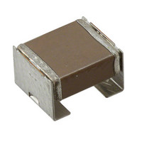
CAP CER KPS 10UF 50V X7R 2220
Manufacturer
Kemet
Series
KPSr
Datasheet
1.C1812C226M4R2C.pdf
(16 pages)
Specifications of C2220C106K5R1CAUTO
Capacitance
10µF
Voltage - Rated
50V
Tolerance
±10%
Temperature Coefficient
X7R
Mounting Type
Surface Mount, MLCC
Operating Temperature
-55°C ~ 125°C
Features
Stacked
Applications
Automotive, Boardflex Sensitive
Ratings
AEC-Q200
Package / Case
2220 (5650 Metric)
Size / Dimension
0.236" L x 0.197" W (6.00mm x 5.00mm)
Thickness
3.50mm
Voltage Rating
50 Volts
Operating Temperature Range
- 55 C to + 125 C
Temperature Coefficient / Code
X7R
Product
Automotive MLCCs
Dimensions
5 mm W x 6 mm L x 3.5 mm H
Termination Style
SMD/SMT
Lead Free Status / RoHS Status
Lead free / RoHS Compliant
Lead Spacing
-
Lead Free Status / Rohs Status
Details
Other names
399-5798-2
C2220C106K5R1CAUTO
C2220C106K5R1CAUTOT500
C2220C106K5R1CAUTO
C2220C106K5R1CAUTOT500


Surface Mount Multilayer Ceramic Chip Capacitors –KPS Series – Commercial Grade (X7R Dielectric)
Soldering Process
Recommended Soldering Technique:
Recommended Soldering Profile
Table 3 – Chip Capacitor Land Pattern Design Recommendations per IPC-7351
Table 4 – Performance & Reliability: Test Methods and Conditions
© KEMET Electronics Corporation • P.O. Box 5928 • Greenville, SC 29606 (864) 963-6300 • www.kemet.com
Resistance to Solvents
EIA Size
High Temperature Life
Temperature Cycling
Moisture Resistance
Mechanical Shock
Code
Terminal Strength
2220
Biased Humidity
1210
1812
Thermal Shock
Ripple Current
Solderability
Storage Life
Board Flex
Stress
• Mounting technique is limited to solder reflow only.
• KEMET recommends following the guidelines outlined in IPC/JEDEC J-STD-020D.1
Metric Size
Code
3225
4532
5650
MIL-STD-202 Method 103
MIL-STD-202 Method 106
MIL-STD-202 Method 107
MIL-STD-202 Method 108
MIL-STD-202 Method 108
MIL-STD-202 Method 213
MIL-STD-202 Method 215
JESD22 Method JA-104
Heat Generation
∆T : 20ºC max.
Reference
JIS-C-6429
JIS-C-6429
J-STD-002
2.87
4.78
1.75
Median (Nominal) Land
X
Protrusion (mm)
1.35
2.08
1.14
Y
Reflow solder the capacitor onto a PC board and apply voltage with 10kHz~1Mhz sine curve.
(Ripple voltage must be < rated voltage)
Appendix 1, Note:Force of 1.8kg for 60 seconds.
Appendix 2, Note:2mm (min) for all except 3mm for C0G.
Magnification 50X. Conditions:
a) Method B, 4 hrs @ 155°C, dry heat @ 235°C
b) Method B @ 215°C category 3
c) Method D, category 3 @ 260°C
1000 Cycles (-55°C to +125°C), Measurement at 24 hrs. +/- 2 hrs after test conclusion.
Load Humidity: 1000 hours 85°C/85%RH and Rated Voltage.Add 100K ohm resistor. Measurement
at 24 hrs. +/- 2 hrs after test conclusion.
Low Volt Humidity:1000 hours 85C°/85%RH and 1.5V.Add 100K ohm resistor.
Measurement at 24 hrs. +/- 2 hrs after test conclusion.
t = 24 hours/cycle.Steps 7a & 7b not required.Unpowered.
Measurement at 24 hrs. +/- 2 hrs after test conclusion.
-55°C/+125°C.Note: Number of cycles required-300, Maximum transfer time-20 seconds, Dwell
time-15 minutes.Air-Air.
1000 hours at 125°C (85°C for X5R, Z5U and Y5V) with 1.5X rated voltage applied.
150°C, 0VDC, for 1000 Hours.
Figure 1 of Method 213, Condition F.
Add Aqueous wash chemical - OKEM Clean or equivalent.
3.00
4.39
5.38
C
Test or Inspection Method
C1020-4 • 6/22/2010
8 8
Related parts for C2220C106K5R1CAUTO
Image
Part Number
Description
Manufacturer
Datasheet
Request
R

Part Number:
Description:
CAP, KEMET #F601BL105K250C
Manufacturer:
Kemet
Datasheet:
Part Number:
Description:
Manufacturer:
Kemet
Datasheet:
Part Number:
Description:
Manufacturer:
Kemet
Datasheet: