B37987F5224K051 EPCOS Inc, B37987F5224K051 Datasheet - Page 14
B37987F5224K051
Manufacturer Part Number
B37987F5224K051
Description
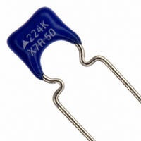
CAP CER .22UF 50V X7R 10% RAD
Manufacturer
EPCOS Inc
Series
B37987Fr
Datasheet
1.B37981F1681K051.pdf
(15 pages)
Specifications of B37987F5224K051
Capacitance
0.22µF
Voltage - Rated
50V
Tolerance
±10%
Temperature Coefficient
X7R
Mounting Type
Through Hole
Operating Temperature
-55°C ~ 125°C
Applications
Automotive
Ratings
AEC-Q200
Package / Case
Radial
Size / Dimension
0.256" L x 0.197" W (6.50mm x 5.00mm)
Thickness
2.50mm Max
Lead Spacing
0.197" (5.00mm)
Lead Style
Flat Bent
Lead Free Status / RoHS Status
Lead free / RoHS Compliant
Features
-
Other names
495-3396-2
B37987F5224K 51
B37987F5224K51
B37987F5224K 51
B37987F5224K51
Available stocks
Company
Part Number
Manufacturer
Quantity
Price


The following should be considered in the placement process
10. When soldering the most gentle solder profile feasible should be selected (heating time, peak
11. Ensure the correct solder meniscus height and solder quantity.
12. Ensure correct dosing of the cement quantity.
13. Ceramic capacitors with an AgPd external termination are not suited for the lead-free solder
This listing does not claim to be complete, but merely reflects the experience of EPCOS AG.
1. Ensure correct positioning of the ceramic capacitor on the solder pad.
2. Caution when using casting, injection-molded and molding compounds and cleaning agents,
3. Support the circuit board and reduce the placement forces.
4. A board should not be straightened (manually) if it has been distorted by soldering.
5. Separate panels with a peripheral saw, or better with a milling head (no dicing or breaking).
6. Caution in the subsequent placement of heavy or leaded components (e.g. transformers or
7. When testing, transporting, packing or incorporating the board, avoid any deformation of the
8. Avoid the use of excessive force when plugging a connector into a device soldered onto the
9. Ceramic capacitors must be soldered only by the mode (reflow or wave soldering) permissible
Multilayer ceramic capacitors
Cautions and warnings
as these may damage the capacitor.
snap-in components): danger of bending and fracture.
board not to damage the components.
board.
for them (see the chapter “Soldering directions”).
temperature, cooling time) in order to avoid thermal stresses and damage.
process: they were developed only for conductive adhesion technology.
13
10/06
Related parts for B37987F5224K051
Image
Part Number
Description
Manufacturer
Datasheet
Request
R

Part Number:
Description:
.022UF 100V 10% MONOLIT CERM CAP
Manufacturer:
EPCOS Inc
Datasheet:
Part Number:
Description:
.033UF 100V 10% MONOLIT CERM CAP
Manufacturer:
EPCOS Inc
Datasheet:
Part Number:
Description:
.047UF 100V 10% MONOLIT CERM CAP
Manufacturer:
EPCOS Inc
Datasheet:
Part Number:
Description:
.068UF 100V 10% MONOLIT CERM CAP
Manufacturer:
EPCOS Inc
Datasheet:
Part Number:
Description:
.10UF 100V 10% MONOLITH CERM CAP
Manufacturer:
EPCOS Inc
Datasheet:
Part Number:
Description:
.15UF 100V 10% MONOLITH CERM CAP
Manufacturer:
EPCOS Inc
Datasheet:
Part Number:
Description:
CAP CERAMIC MONO .1UF 50V 10%
Manufacturer:
EPCOS Inc
Datasheet:
Part Number:
Description:
CAP .068UF 50V CERAMIC MONO 10%
Manufacturer:
EPCOS Inc
Datasheet:
Part Number:
Description:
CAP .15UF 50V CERAMIC MONO 10%
Manufacturer:
EPCOS Inc
Datasheet:
Part Number:
Description:
CAP .22UF 50V CERAMIC MONO 10%
Manufacturer:
EPCOS Inc
Datasheet:

