ECJ-3YB1A106M Panasonic - ECG, ECJ-3YB1A106M Datasheet - Page 6
ECJ-3YB1A106M
Manufacturer Part Number
ECJ-3YB1A106M
Description
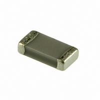
CAP 10UF 10V CERAMIC 1206 X5R
Manufacturer
Panasonic - ECG
Series
ECJr
Datasheets
1.ECJ-RVB1H332M.pdf
(6 pages)
2.ECJ-RVB1H332M.pdf
(2 pages)
3.ECJ-RVB1H332M.pdf
(1 pages)
4.ECJ-RVB1H332M.pdf
(3 pages)
5.ECJ-0EB0J105K.pdf
(6 pages)
Specifications of ECJ-3YB1A106M
Capacitance
10µF
Voltage - Rated
10V
Tolerance
±20%
Temperature Coefficient
X5R
Mounting Type
Surface Mount, MLCC
Operating Temperature
-55°C ~ 85°C
Features
Low ESR
Applications
General Purpose
Package / Case
1206 (3216 Metric)
Size / Dimension
0.126" L x 0.063" W (3.20mm x 1.60mm)
Thickness
1.60mm
Lead Free Status / RoHS Status
Lead free / RoHS Compliant
Ratings
-
Lead Spacing
-
Other names
ECJ3YB1A106M
PCC2178TR
PCC2178TR


8. Protective Coat
9. Dividing/Breaking of PC Boards
Design and specifi cations are each subject to change without notice. Ask factory for the current technical specifi cations before purchase and/or use.
Should a safety concern arise regarding this product, please be sure to contact us immediately.
Load
position
PC
board
(2) Confi rm that the measuring pins have the right tip
When the surface of a PC board on which the Capacitors
have been mounted is coated with resin to protect
against moisture and dust, it shall be confi rmed that
the protective coating which is corrosive or chemically
active is not used, in order that the reliability of the
Capacitors in the actual equipment may not be infl uenced.
Coating materials that expand or shrink also may lead to
damage to the Capacitors during the curing process.
(1) Abnormal and excessive mechanical stress such as
(2) Dividing / Breaking of the PC boards shall be
(3) Examples of PCB dividing/breaking jigs:
Bending of
PC board
Prohibited dividing
The following fi gures are for your reference to avoid
Item
The outline of a PC board breaking jig is shown below.
When PC boards are broken or divided, loading points
shape, are equal in height and are set in the correct
positions.
bending the PC board.
bending or torsion shown below can cause cracking
in the Capacitors.
done carefully at moderate speed by using a jig
or apparatus to prevent the Capacitors on the
boards from mechanical damage.
should be close to the jig to minimize the extent of the
bending
Also, planes with no parts mounted on should
be used as plane of loading, which generates
a compressive stress on the mounted plane, in
order to prevent tensile stress induced by the
bending, which may cause cracks of the Capacitors
or other parts mounted on the PC boards.
Bending
V-groove
Chip
component
PC board
Load adirection
Prohibited setting
Outline of Jig
Separated, Crack
Check pin
PC
board
Recommended dividing
PC board
splitting jig
Torsion
V-groove
Load position
Recommended setting
V-groove
Chip
component
Supporting pin
Load direction
Check pin
– EC53 –
10.Mechanical Impact
■ Other
(1) The Capacitors shall be free from any excessive
(2) When handling PC boards with Capacitors mounted
For special mounting conditions, please contact us.
Precautions for Use above are from
The Technical Report EIAJ RCR -2335 Caution
Guide Line for Operation of Fixed Multilayer
Ceramic Capacitors for Electronic Equipment by
Japan Electronics and Information Technology
Industries Association (March 2002 issued)
Please refer to above technical report for details.
mechanical impact.
The Capacitor body is made of ceramics and may
be damaged or cracked if dropped.
Never use a Capacitor which has been dropped; their
quality may be impaired and failure rate increased.
on them, do not allow the Capacitors to collide with
another PC board.
When mounted PC boards are handled or stored
in a stacked state, impact between the corner of a
PC board and the Capacitor may cause damage or
cracking and can deteriorate the withstand voltage
and insulation resistance of the Capacitor.
Floor
Multilayer Ceramic Capacitors
Crack
Crack
Mounted PCB
00 Sep. 2008
Related parts for ECJ-3YB1A106M
Image
Part Number
Description
Manufacturer
Datasheet
Request
R


Part Number:
Description:
MICROPHONE OMNI 6X2.2MM W/CAP
Manufacturer:
Panasonic - ECG
Datasheet:

Part Number:
Description:
CAP .0018UF 16V PPS FILM 0603 5%
Manufacturer:
Panasonic - ECG

Part Number:
Description:
CAP .01UF 100V PEN FILM 1210 5%
Manufacturer:
Panasonic - ECG
Datasheet:

Part Number:
Description:
CAP .1F 5.5V GOLD SD VERTICAL
Manufacturer:
Panasonic - ECG
Datasheet:

Part Number:
Description:
SUR ABSORBER 14MM 39V 1000A ZNR
Manufacturer:
Panasonic - ECG
Datasheet:

Part Number:
Description:
FILTER LINE 23.3MH 2A
Manufacturer:
Panasonic - ECG
Datasheet:

Part Number:
Description:
BEAD CORE 600 OHM 100MA 0603 SMD
Manufacturer:
Panasonic - ECG
Datasheet:

Part Number:
Description:
SAW FILTER PCS 1960 MHZ 50/150
Manufacturer:
Panasonic - ECG
Datasheet:
Part Number:
Description:
SAW FILTER WCDMA 1950 MHZ 50/50
Manufacturer:
Panasonic - ECG
Datasheet:
Part Number:
Description:
SAW FILTER EGSM 942 MHZ 50/150
Manufacturer:
Panasonic - ECG
Datasheet:
Part Number:
Description:
SAW FILTER DCS 1842 MHZ 50/150
Manufacturer:
Panasonic - ECG
Datasheet:
Part Number:
Description:
POT 1.0M OHM 3MM SEALED SMD 3 TT
Manufacturer:
Panasonic - ECG
Datasheet:

Part Number:
Description:
MODULE POWER DC/DC 48V/28V 600W
Manufacturer:
Panasonic - ECG
Datasheet:
Part Number:
Description:
RES ARRAY 22 OHM 5% 4 RES SMD
Manufacturer:
Panasonic - ECG
Datasheet: