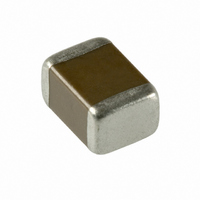
EMK432BJ226KM-T Taiyo Yuden, EMK432BJ226KM-T Datasheet - Page 17

EMK432BJ226KM-T
Manufacturer Part Number
EMK432BJ226KM-T
Description
CAP CER 22UF 16V X5R 1812
Manufacturer
Taiyo Yuden
Series
EMKr
Datasheet
1.UMK107C5105KA-T.pdf
(19 pages)
Specifications of EMK432BJ226KM-T
Capacitance
22µF
Voltage - Rated
16V
Tolerance
±10%
Temperature Coefficient
X5R
Mounting Type
Surface Mount, MLCC
Operating Temperature
-55°C ~ 85°C
Applications
General Purpose
Package / Case
1812 (4532 Metric)
Size / Dimension
0.177" L x 0.126" W (4.50mm x 3.20mm)
Thickness
2.50mm
Lead Free Status / RoHS Status
Lead free / RoHS Compliant
Features
-
Ratings
-
Lead Spacing
-
Other names
587-1472-2
Available stocks
Company
Part Number
Manufacturer
Quantity
Price
Precautions on the use of Multilayer Ceramic Capacitors
4. Soldering
PRECAUTIONS
Stages
1. Since flux may have a significant effect on the performance of
Soldering
Temperature, time, amount of solder, etc. are specified in accor-
dance with the following recommended conditions.
And please contact us about peak temperature when you use
lead-free paste.
Selection of Flux
capacitors, it is necessary to verify the following conditions
prior to use;
(1)Flux used should be with less than or equal to 0.1 wt%
(2)When soldering capacitors on the board, the amount of
(3)When using water-soluble flux, special care should be taken
(equivelent to chroline) of halogenated content. Flux hav-
ing a strong acidity content should not be applied.
flux applied should be controlled at the optimum level.
to properly clean the boards.
Precautions
1-1. When too much halogenated substance (Chlorine, etc.) content is used to activate the
1-2. Flux is used to increase solderability in flow soldering, but if too much is applied, a large
1-3. Since the residue of water-soluble flux is easily dissolved by water content in the air, the
1-1. Preheating when soldering
Heating: Ceramic chip components should be preheated to within 100 to 130C of the sol-
Cooling: The temperature difference between the components and cleaning process should
Ceramic chip capacitors are susceptible to thermal shock when exposed to rapid or concen-
trated heating or rapid cooling. Therefore, the soldering process must be conducted with
great care so as to prevent malfunction of the components due to excessive thermal shock.
Recommended conditions for soldering
Temperature profile
Caution
1. The ideal condition is to have solder mass (fillet) controlled to 1/2 to 1/3 of the thick-
Caution
1. Make sure the capacitors are preheated sufficiently.
2. The temperature difference between the capacitor and melted solder should not be
3. Cooling after soldering should be as gradual as possible.
4. Wave soldering must not be applied to the capacitors designated as for reflow solder-
flux, or highly acidic flux is used, an excessive amount of residue after soldering may
lead to corrosion of the terminal electrodes or degradation of insulation resistance on
the surface of the capacitors.
amount of flux gas may be emitted and may detrimentally affect solderability. To mini-
mize the amount of flux applied, it is recommended to use a flux-bubbling system.
residue on the surface of capacitors in high humidity conditions may cause a degrada-
tion of insulation resistance and therefore affect the reliability of the components. The
cleaning methods and the capability of the machines used should also be considered
carefully when selecting water-soluble flux.
2. Because excessive dwell times can detrimentally affect solderability, soldering dura-
Temperature profile
ness of the capacitor, as shown below:
greater than 100 to 130C
ing only.
[Reflow soldering]
tion should be kept as close to recommended times as possible.
[Wave soldering]
dering.
not be greater than 100C.
Solder
Technical considerations
Capacitor
PC board
TemperaturefCg
TemperaturefCg
300
200
300
100
200
100
0
0
※Ceramic chip components should be preheated to
※Assured to be reflow soldering for 2 times.
※Ceramic chip components should be preheated to
※Assured to be wave soldering for 1 time.
※Except for reflow soldering type.
within 100 to 130C of the soldering.
within 100 to 130C of the soldering.
Preheating
120 sec min
Peak 260C max
Peak 260C max
150C
10 sec max
10 sec max
Preheating
60 sec min
150C
Heating above 230C
40 sec max
4/6
Gradually
Gradually
cooling
cooling
93
4


