SR70.TCT Semtech, SR70.TCT Datasheet

IC TVS ARRAY 2-LINE 300W SOT-143

SR70.TCT

Manufacturer Part Number
SR70.TCT
Description
IC TVS ARRAY 2-LINE 300W SOT-143
Manufacturer
Semtech
Series
RailClamp®r
Datasheet

Specifications of SR70.TCT

Voltage - Reverse Standoff (typ)
70V
Voltage - Breakdown
85V
Power (watts)
300W
Polarization
2 Channel Array - Unidirectional
Mounting Type
Surface Mount
Package / Case
SOT-143, SOT-143B, TO-253AA
Suppressor Type
Diode Arrays
Esd Protection Voltage
15KV@Air Gap/8KV@Contact Disc
Configuration
Dual
Mounting Style
Surface Mount
Clamping Voltage (max)
7VV
Working Voltage (max)
70VV
Leakage Current (max)
5uAA
Operating Temperature Min Deg. C
-55C
Operating Temperature Max Deg. C
125C
Product Length (mm)
3.04(Max)mm
Product Depth (mm)
1.4(Max)mm
Product Height (mm)
1.1mm
Pin Count
3 +Tab
Rad Hardened
No
Lead Free Status / RoHS Status
Lead free / RoHS Compliant
Other names
SR70TR

Available stocks

Company
Part Number
Manufacturer
Quantity
Price
Part Number:
SR70.TCT
Manufacturer:
Semtech
Quantity:
3 000
Part Number:
SR70.TCT
Manufacturer:
SEMTECH/美国升特
Quantity:
20 000
Part Number:
SR70.TCT
Manufacturer:
SEMTECH
Quantity:
11 379
Part Number:
SR70.TCT
Manufacturer:
SEMTECH
Quantity:
17 093
Part Number:
SR70.TCT
Manufacturer:
Semtech
Quantity:
6 430
Part Number:
SR70.TCT
Manufacturer:
SEMTECH
Quantity:
15 225
RailClamps are surge rated diode arrays designed to
protect high speed data interfaces. The SR70 has
been specifically designed to protect sensitive compo-
nents which are connected to data and transmission
lines from over-voltages caused by ESD (electrostatic
discharge), EFT (electrical fast transients), and light-
ning. The SR70 has been optimized for use on ADSL
and other high-speed interfaces.
The unique design of the SR70 integrates four surge
rated, low capacitance steering diodes in a low profile
SOT-143 package. It has a typical capacitance of only
5pF and may be used to protect two high-speed lines
without sacrificing signal integrity. The SR70 is de-
signed to replace “standard” rectifiers that are not
rated for the high energy surges that are normally
expected in telecommunications applications.
During transient conditions, the steering diodes direct
the transient to either the positive side of the power
supply line or to ground. The maximum clamping
voltage seen by the protected circuit will be one diode
drop (V
SR70 may be used as a stand alone device or in
conjunction with TVS diodes for enhanced protection.
Revision 04/18/03
PROTECTION PRODUCTS
Description
Circuit Diagram
F
) above the supply (reference) voltage. The
Pin 2
Pin 4
Pin 1
Pin 3
1
Low Capacitance TVS Diode Array
Features
Mechanical Characteristics
Applications
Schematic & PIN Configuration
Transient protection for high speed data lines to
IEC 61000-4-2 (ESD) ±15kV (air), ±8kV (contact)
IEC 61000-4-4 (EFT) 40A (5/50ns)
IEC 61000-4-5 (Lightning) 1kV, 24A (8/20µs)
Array of surge rated, low capacitance diodes
Protects two I/O lines
Low capacitance (5pF typical) for high-speed
interfaces
Low clamping voltage
Solid-state silicon-avalanche technology
JEDEC SOT-143 package
UL 497B listed
Molding compound flammability rating: UL 94V-0
Marking : R70
Packaging : Tape and Reel per EIA 481
ADSL Lines
I
Video Line Protection
T1/E1 secondary IC Side Protection
Portable Electronics
Microcontroller Input Protection
WAN/LAN Equipment
ISDN S/T Interface
2
C Bus Protection
1
2
SOT-143 (Top View)
4
3
RailClamp
www.semtech.com
SR70

Related parts for SR70.TCT

SR70.TCT Summary of contents

Page 1

... Packaging : Tape and Reel per EIA 481 Applications ADSL Lines Bus Protection Video Line Protection T1/E1 secondary IC Side Protection Portable Electronics Microcontroller Input Protection WAN/LAN Equipment ISDN S/T Interface Schematic & PIN Configuration Pin 3 1 SR70 RailClamp SOT-143 (Top View) www.semtech.com ...

Page 2

... PROTECTION PRODUCTS Absolute Maximum Rating µ Electrical Characteristics (T= 2003 Semtech Corp ° µ µ µ www.semtech.com SR70 ° C ° C ° µ ...

Page 3

... Pulse Duration - tp (µs) Pulse Waveform 110 100 Time (µs) Forward Voltage vs. Forward Current Forward Current - I F 2003 Semtech Corp. 110 100 100 1000 0 Waveform Parameters µ µ -10 -12 -14 - Waveform Parameters µ µ (A) 3 Power Derating Curve 100 125 o Ambient Temperature - T ...

Page 4

... TVS diode may be used as the refer- ence. The steering diodes will begin to conduct when the voltage on the protected line exceeds the working voltage of the TVS (plus one diode drop). 2003 Semtech Corp. SR70 Pin Configuration 1 ) the F ...

Page 5

... PROTECTION PRODUCTS Outline Drawing Notes: (1) Controlling dimension: Inch (unless otherwise specified). (2) Dimension A and B do not include mold protrusions. Mold protrusions are .006” max. Land Pattern 2003 Semtech Corp. 5 SR70 www.semtech.com ...

Page 6

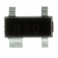
... PROTECTION PRODUCTS Marking Codes R70 SR70 Marking (Top View) Ordering Information Contact Information Phone: (805)498-2111 FAX (805)498-3804 2003 Semtech Corp Semtech Corporation Protection Products Division 200 Flynn Rd., Camarillo, CA 93012 6 SR70 www.semtech.com ...

Related keywords