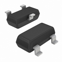
NUP2105LT1G ON Semiconductor, NUP2105LT1G Datasheet - Page 5

NUP2105LT1G
Manufacturer Part Number
NUP2105LT1G
Description
IC CAN BUS PROTECTOR DUAL SOT23
Manufacturer
ON Semiconductor
Datasheet
1.NUP2105LT1G.pdf
(8 pages)
Specifications of NUP2105LT1G
Voltage - Reverse Standoff (typ)
24V
Voltage - Breakdown
26.2V
Power (watts)
350W
Polarization
2 Channel Array - Bidirectional
Mounting Type
Surface Mount
Package / Case
SOT-23-3, TO-236-3, Micro3™, SSD3, SST3
Polarity
Bidirectional
Channels
2 Channels
Clamping Voltage
44 V
Operating Voltage
24 V (Min)
Breakdown Voltage
26.2 V
Termination Style
SMD/SMT
Peak Surge Current
8 A
Peak Pulse Power Dissipation
350 W
Capacitance
30 pF
Maximum Operating Temperature
+ 150 C
Minimum Operating Temperature
- 55 C
Dimensions
1.3 mm W x 2.9 mm L
Lead Free Status / RoHS Status
Lead free / RoHS Compliant
Other names
NUP2105LT1GOSTR
Available stocks
Company
Part Number
Manufacturer
Quantity
Price
Company:
Part Number:
NUP2105LT1G
Manufacturer:
VISHAY
Quantity:
430 000
Company:
Part Number:
NUP2105LT1G
Manufacturer:
ON Semiconductor
Quantity:
182 934
Company:
Part Number:
NUP2105LT1G
Manufacturer:
ON
Quantity:
30 000
Company:
Part Number:
NUP2105LT1G
Manufacturer:
ON
Quantity:
30 000
Part Number:
NUP2105LT1G
Manufacturer:
ON/安森美
Quantity:
20 000
EMI Specifications
be measured using the International Organization for
Standardization (ISO) 7637−1 and −3 specifications that are
representative of various noise sources. The ISO 7637−1
specification is used to define the susceptibility to coupled
transient noise on a 12 V power supply, while ISO 7637−3
defines the noise immunity tests for data lines. The ISO 7637
tests also verify the robustness and reliability of a design by
applying the surge voltage for extended durations.
quantify the EMI immunity level of a CAN system. The IEC
3. Test equipment maximum test voltage is 30 kV.
Table 2. ISO 7637 and IEC 61000−4−X Test Specifications
1. DUT = device under test.
2. The EFT immunity level was measured with test limits beyond the IEC 61000−4−4 test, but with the more severe test conditions of
Table 3. NUP2105L ESD Test Results
ISO 7637−1
12 V Power Supply Lines
ISO 7637−3
Data Line EFT
IEC 61000−4−4
Data Line EFT
IEC 61000−4−5
Human Body Model
IEC 61000−4−2
The EMI protection level provided by the TVS device can
The IEC 61000−4−X specifications can also be used to
ISO 7637−3.
ESD Specification
Test
Waveform
Pulse ‘a’
Pulse ‘b’
Pulse 1
Pulse 2
Contact
Contact
Non−contact (Air Discharge)
t
d_50%
(Level 4 = Severe Industrial
V
open circuit
t
t
f
I
R
t
t
duration
duration
burst
short circuit
Test Specifications
V
duration
duration
t
i
I
duration
open circuit
V
V
short circuit
= 50 W, t
= 50 ns, t
t
repeat
s
s
Environment)
Test
I
I
I
I
V
V
= 2.0 to 5.0 kHz,
max
max
= 0 to −100 V
= 0 to +100 V
max
max
R
s
s
= 5000 pulses
= 5000 pulses
i
= 10 minutes
= 10 minutes
= −60 V
= +40 V
= 50 W
= 300 ms
= 1.2 A
= 0.8 A
= 1 minute
= 1.2 x 50 ms,
= 10 A
= 10 A
http://onsemi.com
= 8 x 20 ms
r
= 2.0 kV
burst
< 5.0 ns,
= 40 A
NUP2105L
= 15 ms,
5
61000−4 and ISO 7637 tests are similar; however, the IEC
standard was created as a generic test for any electronic
system, while the ISO 7637 standard was designed for
vehicular applications. The IEC61000−4−4 Electrical Fast
Transient (EFT) specification is similar to the ISO 7637−1
pulse 1 and 2 tests and is a requirement of SDS CAN
systems. The IEC 61000−4−5 test is used to define the power
absorption capacity of a TVS device and long duration
voltage transients such as lightning. Table 2 provides a
summary of the ISO 7637 and IEC 61000−4−X test
specifications. Table 3 provides the NUP2105L’s ESD
test results.
16 kV
30 kV (Note 3)
30 kV (Note 3)
t
t
d_10%
d_10%
t
d_10%
t
2
t
t
t
R
Ri = 10 W, t
R
duration
duration
t
2
duration
= 200 ms, t
V
V
V
i
i
= 10 ms, t
NUP2105L Test
= 10 W, t
= 50 W, t
clamp
clamp
clamp
= 0.1 ms, t
= 2000 ms, t
I
Test Level
max
I
t
= 50 ms, t
I
max
2
max
(Note 2)
= 200 ms
= 5000 pulses
= 5000 pulses
_
_
_
= 60 minutes
= 1.75 A
max
max
max
= 9.5 A
= 50 A
r
r
r
3
3
= 1.0 ms,
= 1.0 ms,
= 5.0 ns,
= 31 V
= 33 V
= 40 V
= 90 ms
= 100 ms
1
1
1
= 100 ms,
= 2.5 s,
= 2.5 s,
Pass
Pass
Pass
DUT in parallel with
inductive load that is
disconnected from power
supply.
DUT in series with inductor
that is disconnected.
Switching noise of inductive
loads.
Switching noise of inductive
loads.
Lightning, nonrepetitive
power line and load
switching
Simulated Noise Source
Pass / Fail


