DZQA5V6AXV5-7 Diodes Inc, DZQA5V6AXV5-7 Datasheet
DZQA5V6AXV5-7
Specifications of DZQA5V6AXV5-7
Available stocks


Related parts for DZQA5V6AXV5-7


DZQA5V6AXV5-7 Summary of contents
Page 1
... Max (V) (V) Max(μA) 5.6 5.9 1 3.0 = 25°C per Figure 1. A will be 25% of the listed value www.diodes.com DZQA5V6AXV5 QUAD SURFACE MOUNT TVS ARRAY Value Unit 0.9 V Value Unit 380 327 °C/W °C -55 to +150 Clamping Typ Capacitance Typ Capacitance Voltage ...
Page 2
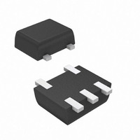
... V , INSTANTANEOUS FORWARD VOLTAGE (V) F Fig. 3 Typical Forward Characteristics Ordering Information (Note 8) Part Number DZQA5V6AXV5-7 Notes: 8. For packaging details our website at http://www.diodes.com/datasheets/ap02007.pdf. Marking Information Date Code Key Year 2009 2010 Code W Month Jan Feb Mar ...
Page 3
... Diodes Incorporated products in such safety-critical, life support devices or systems. Copyright © 2009, Diodes Incorporated www.diodes.com DZQA5V6AXV5 Document number: DS31557 Rev places IMPORTANT NOTICE LIFE SUPPORT www.diodes.com DZQA5V6AXV5 SOT-553 Dim Min Max Typ A 0.55 0.60 0.60 c 0.10 0.18 0.15 D 1.50 1.70 1. ...