ESD7L5.0DT5G ON Semiconductor, ESD7L5.0DT5G Datasheet

TVS ULT LOW CAP SOT-723

ESD7L5.0DT5G

Manufacturer Part Number
ESD7L5.0DT5G
Description
TVS ULT LOW CAP SOT-723
Manufacturer
ON Semiconductor
Datasheet

Specifications of ESD7L5.0DT5G

Voltage - Reverse Standoff (typ)
5V
Voltage - Breakdown
5.4V
Power (watts)
150mW
Polarization
Bidirectional
Mounting Type
Surface Mount
Package / Case
SOT-723
Polarity
Unidirectional
Clamping Voltage
10.4 V
Operating Voltage
5 V
Breakdown Voltage
5.4 V
Termination Style
SMD/SMT
Peak Surge Current
1 A
Capacitance
0.5 pF, 0.25 pF
Maximum Operating Temperature
+ 125 C
Minimum Operating Temperature
- 55 C
Dimensions
0.8 mm W x 1.2 mm L
Lead Free Status / RoHS Status
Lead free / RoHS Compliant
Other names
ESD7L5.0DT5GOSTR

Available stocks

Company
Part Number
Manufacturer
Quantity
Price
Part Number:
ESD7L5.0DT5G
Manufacturer:
ON
Quantity:
8 000
Part Number:
ESD7L5.0DT5G
Manufacturer:
ON Semiconductor
Quantity:
6 300
Part Number:
ESD7L5.0DT5G
Manufacturer:
ON
Quantity:
30 000
Part Number:
ESD7L5.0DT5G
Manufacturer:
ON/安森美
Quantity:
20 000
Company:
Part Number:
ESD7L5.0DT5G
Quantity:
16 000
ESD7L5.0DT5G
Transient Voltage
Suppressors
ESD Protection Diodes with Ultra−Low
Capacitance
components from damage due to ESD in applications that require ultra
low capacitance to preserve signal integrity. Excellent clamping
capability, low leakage and fast response time are combined with an
ultra low diode capacitance of 0.5 pF to provide best in class
protection from IC damage due to ESD. The ultra small SOT−723
package is ideal for designs where board space is at a premium. The
ESD7L5.0DT5G can be used to protect two uni−directional lines or
one bi−directional line. When used to protect one bi−directional line,
the effective capacitance is 0.25 pF. Because of its low capacitance, it
is well suited for protecting high frequency signal lines such as
USB2.0 high speed and antenna line applications.
Specification Features:
Mechanical Characteristics:
CASE:
Epoxy Meets UL 94 V−0
LEAD FINISH:
MOUNTING POSITION:
QUALIFIED MAX REFLOW TEMPERATURE:
Device Meets MSL 1 Requirements
Stresses exceeding Maximum Ratings may damage the device. Maximum
Ratings are stress ratings only. Functional operation above the Recommended
Operating Conditions is not implied. Extended exposure to stresses above the
Recommended Operating Conditions may affect device reliability.
1. FR−5 = 1.0 x 0.75 x 0.62 in.
See Application Note AND8308/D for further description of survivability specs.
© Semiconductor Components Industries, LLC, 2008
October, 2008 − Rev. 3
MAXIMUM RATINGS
IEC 61000−4−2 (ESD)
Total Power Dissipation on FR−5 Board
Storage Temperature Range
Junction Temperature Range
Lead Solder Temperature − Maximum
The ESD7L5.0DT5G is designed to protect voltage sensitive
Low Capacitance 0.5 pF Typical
Low Clamping Voltage
Small Body Outline Dimensions:
Low Body Height: 0.020″ (0.5 mm)
Stand−off Voltage: 5 V
Low Leakage
Response Time is Typically < 1.0 ns
IEC61000−4−2 Level 4 ESD Protection
This is a Pb−Free Device
(Note 1) @ T
(10 Second Duration)
0.047” x 0.047” (1.20 mm x 1.20 mm)
Void-free, transfer-molded, thermosetting plastic
A
100% Matte Sn (Tin)
Rating
= 25°C
Any
Contact
Symbol
°P
T
T
T
stg
D
L
J
°
260°C
−55 to +150
−55 to +125
Value
±10
150
260
1
Unit
mW
kV
°C
°C
°C
†For information on tape and reel specifications,
See specific marking information in the device marking
column of the Electrical Characteristics tables starting on
page 2 of this data sheet.
ESD7L5.0DT5G
including part orientation and tape sizes, please
refer to our Tape and Reel Packaging Specifications
Brochure, BRD8011/D.
PIN 1. CATHODE
Device
DEVICE MARKING INFORMATION
2. CATHODE
3. ANODE
ORDERING INFORMATION
XX = Specific Device Code
M = Date Code
MARKING DIAGRAM
http://onsemi.com
CASE 631AA
1
(Pb−Free)
SOT−723
Package
SOT−723
XX M
1
2
Publication Order Number:
8000/Tape & Reel
Shipping
ESD7L5.0D/D
3

Related parts for ESD7L5.0DT5G

ESD7L5.0DT5G Summary of contents

Page 1

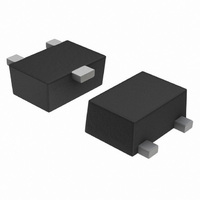
... IC damage due to ESD. The ultra small SOT−723 package is ideal for designs where board space premium. The ESD7L5.0DT5G can be used to protect two uni−directional lines or one bi−directional line. When used to protect one bi−directional line, the effective capacitance is 0.25 pF. Because of its low capacitance well suited for protecting high frequency signal lines such as USB2 ...

Page 2

... R ELECTRICAL CHARACTERISTICS V RWM ( Device Marking Max Device ESD7L5.0DT5G L6 5 measured with a pulse test current Uni−directional capacitance MHz Bi−directional capacitance MHz Surge current waveform per Figure 5. 6. Typical waveform. For test procedure see Figures 3 and 4 and Application Note AND8307/D. Figure 1. ESD Clamping Voltage Screenshot Positive 8 kV contact per IEC 61000− ...

Page 3

... ON Semiconductor has developed a way to examine the entire voltage waveform across the ESD protection diode over the time domain of an ESD pulse in the form of an oscilloscope screenshot, which can be found on the datasheets for all ESD protection diodes ...

Page 4

... X *For additional information on our Pb−Free strategy and soldering details, please download the ON Semiconductor Soldering and Mounting Techniques Reference Manual, SOLDERRM/D. ON Semiconductor and are registered trademarks of Semiconductor Components Industries, LLC (SCILLC). SCILLC reserves the right to make changes without further notice to any products herein ...

Related keywords