SMF5.0AT1 ON Semiconductor, SMF5.0AT1 Datasheet
SMF5.0AT1
Specifications of SMF5.0AT1
Available stocks


Related parts for SMF5.0AT1


SMF5.0AT1 Summary of contents
Page 1
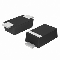
... SMF5.0AT1 Series Zener Transient Voltage Suppressor SOD−123 Flat Lead Package The SMF5.0A Series is designed to protect voltage sensitive components from high voltage, high energy transients. Excellent clamping capability, high surge capability, low zener impedance and fast response time. Because of its small size ideal for use in cellular phones, portable devices, business machines, power supplies and many other industrial/consumer applications ...
Page 2
... Maximum Reverse Leakage Current @ Breakdown Voltage @ Test Current T I Forward Current F V Forward Voltage @ 1/2 sine wave (or equivalent square wave 8.3 ms, duty cycle = 4 pulses per minute maximum. SMF5.0AT1 Series ( unless A V RWM http://onsemi.com 2 Symbol Value P 175 pk P 200 pk P 1000 ...
Page 3
... A transient suppressor is normally selected according to the Working Peak Reverse Voltage (V than the DC or continuous peak operating voltage level measured at pulse test current I at ambient temperature Surge current waveform per Figure 2 and derate per Figure 3. SMF5.0AT1 Series = 30 C unless otherwise noted 1.25 Volts @ 200 mA (V) (Note 6) ...
Page 4
... Figure 1. Pulse Rating Curve 100 t PEAK VALUE RSM 90 PULSE WIDTH ( THAT POINT WHERE THE 70 PEAK CURRENT DECAY = HALF VALUE I RSM TIME (ms) Figure Pulse Waveform SMF5.0AT1 Series TYPICAL PROTECTION CIRCUIT Z in LOAD 100 1000 10,000 0 Figure 1000 ms Pulse Waveform 160 140 ) IS DEFINED P 120 100 / ...
Page 5
... D, DUTY CYCLE (%) Figure 5. Typical Derating Factor for Duty Cycle 1.2 1.0 0.8 0.6 0.4 0.2 0 − TEMPERATURE ( C) Figure 7. Forward Voltage SMF5.0AT1 Series 3 2.5 2 PULSE WIDTH 0.5 100 100 25 50 Figure 6. Steady State Power Derating 1000 100 ...
Page 6
... When using infrared heating with the reflow soldering method, the difference shall be a maximum SMF5.0AT1 Series interface between the board and the package. With the correct pad geometry, the packages will self align when subjected to a solder reflow process. ...
Page 7
... Transient Voltage Suppressor − Surface Mounted 200 Watt Peak Power B A POLARITY INDICATOR OPTIONAL AS NEEDED L J SMF5.0AT1 Series OUTLINE DIMENSIONS SOD−123FL CASE 498−01 ISSUE http://onsemi.com 7 NOTES: 1. DIMENSIONING AND TOLERANCING PER ANSI Y14.5M, 1982. 2. CONTROLLING DIMENSION: MILLIMETER. 3. DIMENSIONS A AND B DO NOT INCLUDE MOLD FLASH ...
Page 8
... Fax: 303−675−2176 or 800−344−3867 Toll Free USA/Canada Email: ONlit@hibbertco.com N. American Technical Support: 800−282−9855 Toll Free USA/Canada SMF5.0AT1 Series JAPAN: ON Semiconductor, Japan Customer Focus Center 2−9−1 Kamimeguro, Meguro−ku, Tokyo, Japan 153−0051 Phone: 81−3−5773−3850 ON Semiconductor Website: http://onsemi ...