SMF5.0AT1G ON Semiconductor, SMF5.0AT1G Datasheet
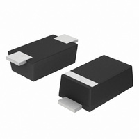
TVS ZENER 200W 5V SOD123FL

SMF5.0AT1G

Manufacturer Part Number
SMF5.0AT1G
Description
TVS ZENER 200W 5V SOD123FL
Manufacturer
ON Semiconductor
Datasheet

Specifications of SMF5.0AT1G

Voltage - Reverse Standoff (typ)
5V
Voltage - Breakdown
6.4V
Power (watts)
200W
Polarization
Unidirectional
Mounting Type
Surface Mount
Package / Case
SOD-123 Flat Leads
Polarity
Unidirectional
Channels
1 Channel
Clamping Voltage
9.2 V
Operating Voltage
5 V
Breakdown Voltage
7 V
Termination Style
SMD/SMT
Peak Surge Current
21.7 A
Peak Pulse Power Dissipation
1000 W
Capacitance
15 pF
Maximum Operating Temperature
+ 150 C
Minimum Operating Temperature
- 55 C
Dimensions
1.65 mm W x 2.7 mm L
Lead Free Status / RoHS Status
Lead free / RoHS Compliant
Other names
SMF5.0AT1GOS
SMF5.0AT1GOS
SMF5.0AT1GOSTR

Available stocks

Company
Part Number
Manufacturer
Quantity
Price
Part Number:
SMF5.0AT1G
Manufacturer:
ON Semiconductor
Quantity:
6
Part Number:
SMF5.0AT1G
Manufacturer:
ON
Quantity:
30 000
Part Number:
SMF5.0AT1G
Manufacturer:
ON
Quantity:
30 000
Part Number:
SMF5.0AT1G
Manufacturer:
ON/安森美
Quantity:
20 000
SMF5.0AT1 Series
200 W Transient
Voltage Suppressor
SOD-123 Flat Lead Package
components from high voltage, high energy transients. Excellent
clamping capability, high surge capability, low zener impedance and
fast response time. Because of its small size, it is ideal for use in
cellular phones, portable devices, business machines, power supplies
and many other industrial/consumer applications.
Features
Mechanical Characteristics:
CASE:
Epoxy Meets UL 94 V-0
LEAD FINISH:
MOUNTING POSITION:
QUALIFIED MAX REFLOW TEMPERATURE:
Device Meets MSL 1 Requirements
© Semiconductor Components Industries, LLC, 2007
September, 2007 - Rev. 3
The SMF5.0A Series is designed to protect voltage sensitive
Stand-off Voltage: 5 - 58 Volts
Peak Power - 200 Watts @ 1 ms (SMF5.0A - SMF58A)
Low Leakage
Response Time is Typically < 1 ns
ESD Rating of Class 3 (> 16 kV) per Human Body Model
ESD Rating of Level 4 (8 kV Contact Discharge) per IEC61000-4-2
EFT (Electrical Fast Transients) Rating of 40 A per IEC61000-4-4
Low Profile - Maximum Height of 1.0 mm
Small Footprint - Footprint Area of 8.45 mm
Supplied in 8 mm Tape and Reel - 3,000 Units per Reel
Cathode Indicated by Polarity Band
Lead Orientation in Tape: Cathode Lead to Sprocket Holes
Pb-Free Packages are Available
Void‐free, transfer‐molded, thermosetting plastic
100% Matte Sn (Tin)
Any
260°C
2
1
†For information on tape and reel specifications,
See specific marking information in the device marking
column of the Electrical Characteristics table on page 3 of
this data sheet.
SMFxxxAT1G
including part orientation and tape sizes, please
refer to our Tape and Reel Packaging Specifications
Brochure, BRD8011/D.
Device
PLASTIC SURFACE MOUNT
TRANSIENT SUPPRESSOR
(Note: Microdot may be in either location)
DEVICE MARKING INFORMATION
200 WATT PEAK POWER
CATHODE
xx
M
G
1
ZENER OVERVOLTAGE
ORDERING INFORMATION
1
= Device Code (Refer to page 3)
= Date Code
= Pb-Free Package
MARKING DIAGRAM
http://onsemi.com
5 - 58 VOLTS
SOD-123FL
(Pb-Free)
Package
1: CATHODE
2: ANODE
xx M G
Publication Order Number:
G
SOD-123FL
CASE 498
PLASTIC
3000/Tape & Reel
ANODE
Shipping
2
SMF5.0AT1/D
2

Related parts for SMF5.0AT1G

SMF5.0AT1G Summary of contents

Page 1

SMF5.0AT1 Series 200 W Transient Voltage Suppressor SOD-123 Flat Lead Package The SMF5.0A Series is designed to protect voltage sensitive components from high voltage, high energy transients. Excellent clamping capability, high surge capability, low zener impedance and fast response time. ...

Page 2

MAXIMUM RATINGS Rating Dissipation (PW-10/1000 ms) (Note 1) SMF5.0A - SMF58A Maximum 25°C, (PW-8/20 ms) (Note 2) Maximum P Dissipation @ Power Dissipation @ T = 25°C (Note 3) A Derate above 25°C ...

Page 3

ELECTRICAL CHARACTERISTICS V RWM (Note 5) Device* Marking SMF5.0A SMF6.0A SMF6.5A 6.5 SMF7.0A SMF7.5A 7.5 SMF8.0A SMF8.5A 8.5 SMF9.0A ...

Page 4

V 10,000 1000 100 10 1.0 10 100 t , PULSE WIDTH (ms) P Figure 1. Pulse Rating Curve 100 @ PEAK VALUE I r RSM 90 PULSE WIDTH ( THAT POINT WHERE THE 70 ...

Page 5

D, DUTY CYCLE (%) Figure 5. Typical Derating Factor for Duty Cycle 1.2 1.0 0.8 0.6 0.4 0 TEMPERATURE ...

Page 6

... Pb-Free strategy and soldering details, please download the ON Semiconductor Soldering and Mounting Techniques Reference Manual, SOLDERRM/D. N. American Technical Support: 800-282-9855 Toll Free  USA/Canada Europe, Middle East and Africa Technical Support:   ...

Related keywords