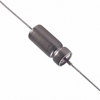
T197A106K050AS Kemet, T197A106K050AS Datasheet - Page 4

T197A106K050AS
Manufacturer Part Number
T197A106K050AS
Description
CAP TANT-WET 10UF 50V 10% AXIAL
Manufacturer
Kemet
Series
T197r
Type
Hermetically Sealedr
Datasheet
1.T197A566K008AS.pdf
(28 pages)
Specifications of T197A106K050AS
Capacitance
10µF
Voltage - Rated
50V
Tolerance
±10%
Esr (equivalent Series Resistance)
5.310 Ohm
Operating Temperature
-55°C ~ 200°C
Mounting Type
Through Hole
Package / Case
Axial
Size / Dimension
0.219" Dia x 0.453" L (5.56mm x 11.51mm)
Manufacturer Size Code
A
Features
Wet Tantalum
Lead Free Status / RoHS Status
Contains lead / RoHS non-compliant
Height
-
Lead Spacing
-
Other names
399-3405
T197A106K050AS7340
T197A106K050AS7340
4
6. Dissipation Factor (DF
volt rms applied. Note that, in either operation, peak AC
plus DC bias must not exceed either rated voltage
Measurement circuits are of high impedance, however,
and under these conditions 1 volt rms may be applied
even to 6 volt capacitors (23% peak reversal) without a
DC bias. DC bias is thus normally not used, except
when rated voltage is below 6 volts and the AC signal
level exceeds 0.3 vrms. However, MIL-PRF-39006 pro-
vides for up to 2.2 volts DC. DC bias is not commonly
used at room temperature, but is more commonly used
at elevated temperatures.
measure of the resistive component in capacitors. It is
the ration of the unavoidable resistance to the capaci-
tive reactance, usually expressed in percent. DF
increases with temperature above +25°C and may also
increase at lower temperatures. Unfortunately, one
general limit for DF cannot be specified for all capaci-
tance/voltage combinations, nor can response to tem-
perature be simply stated. Catalogs for the respective
series list DF limits under various conditions.
quency as would be expected from the decreasing
capacitive reactance. DF is not a very useful parame-
ter above about 1 kHz. The DF of larger capacitance
values increases more rapidly than that of smaller rat-
ings.
up to about 2% when full rated voltage is applied, as
bias, DF is also reduced by the presence of DC bias.
Rated voltage may cause a decrease in DF of about
0.2% (e.g., a decrease from 3.6 to 3.4% DF).
sionally, as tan d or “loss tangent.” The Quality Factor”,
Q, is the reciprocal of DF (DF is not expressed in per-
cent in this calculation). Another expression, rarely
used is the “power factor,” or ESR. Power factor is cos
Ø, while DF is cot Ø.
7. DC Leakage (DCL)
extent, and this effect can frequently be used to advan-
tage in circuits where only very low leakage currents
can be tolerated.
Figure 2. Typical Effect of Temperature upon DC
Leakage Current
DF is measured at 120 Hz and 25°C with up to 1
Dissipation Factor (DF) is a useful low-frequency
Dissipation factor increases with increasing fre-
DC bias causes a small reduction in capacitance,
DF is defined as ESR and is also referred to occa-
DC leakage is affected by voltage to a much larger
X c
© KEMET Electronics Corporation, P.O. Box 5928, Greenville, SC 29606 (864) 963-6300
Z
)
DC leakage current (DCL) increases with increasing
temperature according to the typical curve of Figure 2.
through +85°C and may also be measured at +125°C
with 2/3 of rated voltage applied.
8. Rated Voltage
working voltage permissible at temperatures of +85°C or
below. The lower operating temperature is specified
as -55°C. Operation above +85°C is permissible, with
reduced working voltage. The typical working voltage
reduction is to 2/3 of rated voltage at +125°C.
9. Working Voltage
ating voltage for continuous duty at or below 85°C with-
out DC voltage surges or AC ripple superimposed. No
voltage derating is required below 85°C. Capacitors may
be operated to 125°C with working voltage linearly der-
ated to 2/3 of the 85°C rating at 125°C.
Figure 3. Working Voltage Change with Temperature
10. Surge Voltage
to which the capacitor should be subjected under tran-
sient conditions, including peak AC ripple and all DC
transients.
Table 1. Surge Voltage Ratings
with the applicable surge voltage per Table 1. The
surge voltage is applied for 1000 cycles of 30 seconds
on voltage through a 1000 ± 100 ohm series resistor
and 30 seconds off voltage with the capacitor dis-
charged through a 1,000 ohm resistor. Upon complet-
ing the test, the capacitors are allowed to stabilize at
room temperature. Capacitance, DF, and DCL are then
tested:
DC Working
Voltage @ 85°C
Surge Voltage
Leakage current is measured at a rated voltage
This term refers to the maximum continuous DC
This is the maximum recommended peak DC oper-
Surge Voltage is defined as the maximum voltage
A typical surge voltage test is performed at +85°C
1. The DCL should not exceed the initial 25°C limit.
2. The capacitance should be within ±2% of initial
3. The DF should not exceed the initial 25°C limit.
value.
6.9 9.2 11.5 17.2 28.8 34.5 57.5 69 86.2 115 144
6
8
10
15
25
30
50
60
75 100 125


