3120-F311-P7T1-W01D-20A E-T-A, 3120-F311-P7T1-W01D-20A Datasheet
3120-F311-P7T1-W01D-20A
Specifications of 3120-F311-P7T1-W01D-20A
3120-F311-P7T1-W01D-20AMP


Related parts for 3120-F311-P7T1-W01D-20A


3120-F311-P7T1-W01D-20A Summary of contents
Page 1
... Illumination is optional and there is a range of colours and markings for the rocker. Under overload conditions the rocker returns to the OFF position. 6-way frame for 3120-F5 available upon request. Any one of the following additional function modules can be supplied factory fitted to the rear of the switch/circuit breaker. ● ...
Page 2
... Rocker markings Rocker illumination (optional 3120 - 3120 - N.B. Switch only versions must be specified with -N7 or -G7 terminals. Terminals 12(k) and 22(k) are not fitted Typical time/current characteristics single or double pole load 0.1 … panel thickness 1-4 mm (.039-.157 in) 1.2-2.4 mm (.047-.094 in) (terminals 11,12k,12i) 2.5 … ...
Page 3
... Thermal Overcurrent Circuit Breaker 3120-F... Internal connection diagrams 2-pole, 2-pole, thermally protected on both poles thermally protected on one pole only line 11 21 12(i) 22(i) 12(k) 22(k) load 1-pole, 2-pole, thermally protected unprotected line 11 12(i) 22(i) 12(k) load Dimensions Style F3.1 collar height 1 mm/.039 in. ...
Page 4
... X 221 619 01 48 1.89 ø8 .315 ø4.4 .173 60 2.36 73 2.87 6-way frame for 3120-F5... upon request Cut-out dimensions Cut-out for mounting style -F3 with rocker and push button - 0.4 -.016 - 0.2 -.008 min. 2.5 min .098 max. R2 max .079 ± ...
Page 5
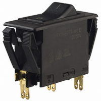
... Thermal Overcurrent Circuit Breaker 3120-F7.. Description E-T-A’s proven type 3120 in a new attractive styling (S-type TO CBE to EN 60934 with trip free mechanism) offering the choice of single pole, double pole with single pole protection, and double pole with protection on both poles. Designed for snap-in panel mounting with illumination as an option. ...
Page 6
... Rocker markings Q "I" and "0" moulded in Push button illumination (optional 3120 - 3120 - N.B. Switch only versions must be specified with -N7 or -G7 terminals. Terminals 12(k) and 22(k) are not fitted Typical time/current characteristics single or double pole load 0.1 … panel thickness ...
Page 7
... Thermal Overcurrent Circuit Breaker 3120-F7.. Dimensions Style -F7.N and F7.R 25 .984 15.5 .610 12(i) 10.7 3.5 .421 .138 21 15.5 .610 .827 blade terminals DIN 46244-C-Ms-S ( .110) flat head screw ISO1580 M3.5x5-MS tightening torque max. 0.8 Nm Style -F7.P and F7.S 34 1.34 18.8 ...
Page 8
... Thermal Overcurrent Circuit Breaker 3120-F7.. Insulated cover Y 303 068 .787 Terminal adapter Y 303 862 01 4 .157 blade terminal DIN 46244-C-Ms-S (QC 2x.110) Spacer Y 303 676 01 52 2.05 44.5 1.75 1 .039 sharp-edged without bends Rear terminal shroud black (IP64) Y 304 275 01 40.5 +0.5 1 ...
Page 9
... Thermal Overcurrent Circuit Breaker 3120-F... Description Switch/thermal trip free circuit breaker (S-type TO CBE to EN 60934) with standard isolator style two button operation. Single button press-to-reset version also available. Both types can be supplied in single pole configuration only, in double pole with single pole protection, and in double pole with protection on both poles ...
Page 10
... WRX white translucent/red WBX white translucent/black Push button illumination (optional 3120 - GRX 3120 - ... . . - 20 A N.B. Switch only versions must be specified with -N7 or -G7 terminals. Terminals 12(k) and 22 (k) are not fitted Typical time/current characteristics single or double pole load 0.1 … 2.5 … ...
Page 11
... Thermal Overcurrent Circuit Breaker 3120-F... Dimensions 3120-F3.F-…-S… actuating force max OFF position optional illumination in ON position 25 .984 16.2 .638 12(i) 12(k) 10.7 3.5 .421 .138 21 15.5 .827 .610 blade terminals DIN 46244-C-Ms-S (QC 2x .110) flat head screw ISO1580 M3.5x5-MS tightening torque max. 0.8 Nm 3120-F3.G-… ...
Page 12
... Accessories Rear terminal shroud black (IP64) Y 304 275 01 2.5 .098 Water splash cover, transparent (IP66) for style 3120-F2.F-... X 221 619 01 consisting of - retaining clip Y 306 551 01 - cover Y 306 001 303 675 01 suitable for panel thickness < (.079 in 303 675 02 suitable for panel thickness < ...
Page 13
... Auxiliary Contact Module X3120-S for circuit breaker 3120-F... Description A module supplied factory fitted to type 3120-F to provide electrically separate changeover contacts which operate as the main contacts open/ close. Ideally suited to status signalling and sequence switching. Typical applications Monitoring of the switching position of the circuit breaker or any connected load ...
Page 14
... Undervoltage Release Module X3120-U...for circuit breaker 3120-F... Description A module suitable for all double pole versions of type 3120-F to trip the main switch/circuit breaker mechanism in the event of loss of voltage. When the voltage is restored the rocker switch must be reset to reconnect the load, thereby avoiding the safety hazards associated with automatic re-starting of machinery ...
Page 15
... Remote Trip Module X3120-M... for circuit breaker 3120-F... Description A module which adds remote trip capability to all versions of type 3120-F. A voltage applied across the coil, by means of an external sensor for example, will cause disconnection of the main switch/circuit breaker mechanism. Typical applications Electrical monitoring of safety systems, remote trip. ...
Page 16
... Mechanical Slide Interlock Module X3120-V...for circuit breaker 3120-F... Description Suitable for use with all type 3120-F versions, this module provides a mechanical safety interlock which, according to the option specified, prevents the main switch/circuit breaker mechanism from being reset/switched on. The actuator is intended for use with interlock systems to ensure that machinery cannot be operated without covers and safety guards in place, for instance ...