3120-F321-P7T1-W01D-15A E-T-A, 3120-F321-P7T1-W01D-15A Datasheet - Page 10
3120-F321-P7T1-W01D-15A
Manufacturer Part Number
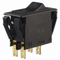
3120-F321-P7T1-W01D-15A
Description
CIRCUIT BREAKER ROCKER 15 AMP
Manufacturer
E-T-A
Series
3120-Fr
Datasheet
1.3120-F311-P7T1-W01D-20A.pdf
(16 pages)
Specifications of 3120-F321-P7T1-W01D-15A
Breaker Type
Thermal
Voltage
50VDC, 250VAC
Current - Trip (it)
15A
Number Of Poles
2
Actuator Type
Rocker
Mounting Type
Panel Mount
Lead Free Status / RoHS Status
Lead free / RoHS Compliant
Other names
302-1203
3120-F321-P7T1-W01D-15AMP
3120F321P7T1W01D-15A
3120F321P7T1W01D1
3120F321P7T1W01D1
Q1159218
3120-F321-P7T1-W01D-15AMP
3120F321P7T1W01D-15A
3120F321P7T1W01D1
3120F321P7T1W01D1
Q1159218


1
Type No.
3120
3120 - F 3 2 F - N7 T1 - S GRX L 4 - 10 A
3120 - F 3 0 F - N7 Q1 - S
N.B.
Switch only versions must be specified with -N7 or -G7 terminals.
Terminals 12(k) and 22 (k) are not fitted.
1 - 68
Ordering information
push button switch/circuit breaker
Mounting
F
snap in frame
Size of frame
2
3
flange mounting, special frame for fitting splash cover
to fit mounting cut-out 50.5 x 21.5 mm (1.99 x 8.47 in)
panel thickness 1 - 6.35 mm (.039 - .250 in)
Number of poles
0
1
2
5
6
2-pole, unprotected, switch only
1-pole, thermally protected
2-pole, thermally protected
2-pole, thermally protected on one pole only (terminals 11,12k,12i)
1-pole, unprotected, switch only
Mounting frame design
F
G
with 2 push buttons
with 1 push button (switch-on only)
Terminal configuration
P7
H7
N7
G7
blade terminals 2x2.8x0.8 mm (QC 2x.110)
(terminals 12(k), 22(k), 11, 21), not for under voltage
module, not for switch
12(k), 22(k): blade terminals 2x2.8-0.8 (QC 2x.110)
11, 21: terminal screws, not for switch
as P7, but including shunt terminals 12(i) and 22(i)
as blade terminals 2x2.8x0.8 mm (QC 2x.110)
not for under voltage module
as H7, but including shunt terminals 12(i) and 22(i)
as blade terminals 2x2.8x0.8 mm (QC 2x.110)
Characteristic curve
T1
Q1
Thermal Overcurrent Circuit Breaker 3120-F...
thermal, 1.01-1.4 I
switch only, only for N7 or G7 terminals
Switch style/colour
D
Z
S
1 push button (re-set only)
1 push button (momentary switch)
01X
04X
12X
19X
2 push buttons on/off
GRX
WRX
WBX
...
black
red
white translucent
green translucent
green translucent/red
white translucent/red
white translucent/black
Push button illumination (optional)
B
L
G
Y
R
. . - 20 A
filament AC/DC
neon, AC
green LED, AC/DC
yellow LED, AC/DC
red LED, AC/DC
Illumination voltage range (optional)
0
1
2
3
4
5
4 - 7 V (B,G,Y,R)
10 - 14 V (B,G,Y,R)
20 - 28 V (B,G,Y,R)
90 - 140 V (L)
185 - 275 V (L)
42 - 54 V (B,Y,R)
Current ratings
0.1...20 A
N
ordering example
switch only
www.e-t-a.com
Typical time/current characteristics
The time/current characteristic curve depends on the ambient temperature
prevailing. In order to eliminate nuisance tripping, please multiply the circuit
breaker current ratings by the derating factor shown below. See also
section 9 – Technical information.
Ambient temperature °F
Derating factor
single or double pole load
0.1 … 2 A
2.5 … 20 A
10000
10000
1000
1000
100
100
0.1
0.1
10
10
1
1
1
1
°C
2
2
… times rated current
… times rated current
-22 -4
-30 -20
0.8 0.76 0.84 0.92 1
4
4
6
6
8 10
8 10
+14 +32 +73.4 +104 +122 +140
-10
0
20
20
+23
40
40
+40 +50
1.08 1.16 1.24
Issue B
+73.4 °F
+73.4 °F
+140 °F
+140 °F
+23 °C
+60 °C
+60 °C
+23 °C
-30 °C
(230209)
-30 °C
-22 °F
-22 °F
+60
Related parts for 3120-F321-P7T1-W01D-15A
Image
Part Number
Description
Manufacturer
Datasheet
Request
R

Part Number:
Description:
CIRCUIT BREAKER ROCKER DP12A
Manufacturer:
E-T-A
Datasheet:
Part Number:
Description:
CIRCUIT BREAKER DP 10A WHT ILL
Manufacturer:
E-T-A
Datasheet:
Part Number:
Description:
CIRCUIT BRKR ROCKER 2P 2.5A RED
Manufacturer:
E-T-A
Datasheet:
Part Number:
Description:
CIRCUIT BREAKER ROCKER DP 5A BK
Manufacturer:
E-T-A
Datasheet:
Part Number:
Description:
CIRCUIT BRKER RCKR DP 15A GRN
Manufacturer:
E-T-A
Datasheet:
Part Number:
Description:
CIRCUIT BREAKER DP 10A GRN LED
Manufacturer:
E-T-A
Datasheet:
Part Number:
Description:
CIRCUIT BREAKER DP 10A GREEN ILL
Manufacturer:
E-T-A
Datasheet:

Part Number:
Description:
CIRCUIT BREAKER ROCKER DP 10A BK
Manufacturer:
E-T-A
Datasheet:

Part Number:
Description:
CIRCUIT BREAKER ROCKR DP 15A WHT
Manufacturer:
E-T-A
Datasheet:
Part Number:
Description:
CIRCUIT BREAKER ROCKR DP 20A WHT
Manufacturer:
E-T-A
Datasheet:
Part Number:
Description:
CIRCUIT BREAKER ROCKER DP 20A BK
Manufacturer:
E-T-A
Datasheet:
Part Number:
Description:
CIRCUIT BREAKER ROCKER DP 2A BK
Manufacturer:
E-T-A
Datasheet:

Part Number:
Description:
CIRCUIT BREAKER VERT PCB 8A
Manufacturer:
E-T-A
Datasheet:
Part Number:
Description:
CIRCUIT BREAKER VERT PCB 5A
Manufacturer:
E-T-A
Datasheet:
Part Number:
Description:
Circuit Breaker, Single Pole, 250VAC 48 VDC, 0.05A
Manufacturer:
E-T-A Circuit Protection & Control