1776905-1 Tyco Electronics, 1776905-1 Datasheet - Page 9
1776905-1
Manufacturer Part Number
1776905-1
Description
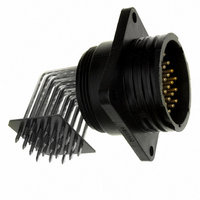
CONN RCPT 23-24POS R/A CPC SER 1
Manufacturer
Tyco Electronics
Series
CPC Series 1r
Datasheet
1.1-601967-6.pdf
(51 pages)
Specifications of 1776905-1
Connector Type
Receptacle, Male Pins
Number Of Positions
24
Shell Size - Insert
23-24
Mounting Type
Panel Mount, Flange; Through Hole, Right Angle
Termination
Solder
Fastening Type
Threaded
Orientation
Keyed
Shell Material, Finish
Thermoplastic
Lead Free Status / RoHS Status
Lead free / RoHS Compliant
Features
-
Ingress Protection
-
Shell Size, Military
-
Other names
A98557


Current Rating
The presentation of current-
carrying capacity in AMP
product specifications includes
two parts:
I
I
Practical Values
The current-rating method
gives designers practical
values applicable to their appli-
cations. While the specified
current levels for a contact may
be lower than for other testing
methods, they are more practi-
cal and simplify the system
design process.
“Spec-manship” is replaced
by a realistic assessment of the
current-carrying capacity of a
contact under varying condi-
tions of temperature, connector
loading, and wire size.
Specific current-carrying data
based on EOL and % loading is
available from Tyco Electronics.
Please contact your local
Tyco Electronics Sales Engineer
or call Tyco Electronics.
Connector/Contact Acceptability
As previously stated, choosing
the correct connector/contact
combination is fundamental
to the successful function of
all connectors. The Selector
Chart shown at right, is
designed to simplify your choice
Catalog 82021
Revised 7-07
www.tycoelectronics.com
First, a base curve showing
current levels versus T-rise for
a single circuit and the largest
wire size (See figure 1). This
represents the maximum
current capacity of the
contact. The curve is usually
flat up to 75°C ambient and
then drops off. Up to 75°C, the
30°C T-rise limits the amount
of current, and above 75°C
the current must be reduced
to keep the combination of
ambient temperature and
T-rise from exceeding the
maximum operating tempera-
ture of 105°C.
Next are rating factors, a
table of multipliers to account
for connector loading and for
smaller wire sizes (See figure 2).
The designer first determines
the base current for the
ambient conditions of the
application; then multiplies
this base current by the rating
factors to find the current
level for the application’s
loading factor and wire size.
Dimensions are in inches and
millimeters unless otherwise
specified. Values in brackets
are metric equivalents.
AMP Circular Connectors for
Commercial Signal and Power Applications
Presentation — An Example*
of connectors and their accept-
able contacts. Once you have
selected the wire size, current-
carrying capacity need,
number of positions required,
and the type of contacts
needed in your choice of
connector, refer to this matrix
for a quick look at exactly what
is acceptable in a given
connector type.
*Note: Data is not typical of a
specific CPC connector configu-
ration. For specific current
rating information based on %
connector loading, contact
Tyco Electronics.
To demonstrate the method of
specifying current, consider the
following application conditions;
an ambient temperature of 65°C,
a 50% loading of contacts in
the housing, and 20 AWG
[0.6mm
I
I
I
I
I
Contact Selector Chart
The specific rating for this
application is the product of
the base rating and the rating
factor:
CMC Series 1
CMC Series 2
CMC Series 3
CMC Series 4
From Figure 1, the base
current rating is 14 ampere
with 18 AWG [0.8mm
Figure 2, the rating factor for
50% loading and 20 AWG
[0.6mm
Each of the contacts can
carry 9.5 ampere.
However, if the ambient temper-
ature is 80°C the allowable
T-rise becomes 25°C. The base
current must be lowered to
12.8 ampere so that the 105°C
maximum operating tempera-
ture is not exceeded. The
current rating then becomes:
CPC Series 1
CPC Series 2
CPC Series 3
CPC Series 4
CPC Series 5
CPC Series 6
CPC 5015
Connector
12.8 x 0.68 = 8.7 ampere.
14 x 0.68 = 9.5 ampere
Type
2
] wire.
2
] wire is 0.68.
20 DF
Dimensions are shown for
reference purposes only.
Specifications subject
to change.
2
] wire.
Type I
Type II
0
Graph shows the relationship between base current, ambient
temperature, and contact T-rise.
Rating factors allow the base current to be adjusted for various
connector loading and wire sizes.
10
Single
100%
30%
50%
70%
USA: 1-800-522-6752
Canada: 1-905-470-4425
Mexico: 52-55-1106-0800
C. America: 57-1-254-4444
Type III+
20
30
.97
.83
.65
.55
Note:
are RoHS Compliant.
18
1
Ambient Temperature (°C)
Type III+
40
Posted
All part numbers
.83
.80
.68
.53
.45
20
50
Figure 1
Figure 2
60
Type XII
AWG
.69
.66
.57
.45
.38
22
70
South America: 55-11-2103-6000
Hong Kong: 852-2735-1628
Japan: 81-44-844-8013
UK: 44-208-420-8341
.59
.57
.48
.38
.32
24
Sub-Mini
80
Coax
Single Contact
90
18 AWG
.50
.49
.42
.33
.28
26
100
POWERBAND
Contacts
15
10
5
0
9
Related parts for 1776905-1
Image
Part Number
Description
Manufacturer
Datasheet
Request
R

Part Number:
Description:
Battery Interconnection System for Portable Electronics; BU CONN FS6 8POS DIP TYPE ASSY ( AMP )
Manufacturer:
Tyco Electronics
Part Number:
Description:
Manufacturer:
Tyco Electronics
Datasheet:
Part Number:
Description:
Manufacturer:
Tyco Electronics
Datasheet:


