JBXED0G07FSSDPR Souriau Connection Technology, JBXED0G07FSSDPR Datasheet - Page 16
JBXED0G07FSSDPR
Manufacturer Part Number
JBXED0G07FSSDPR
Description
CONN RCPT PROTRUDING 7POS SOLDER
Manufacturer
Souriau Connection Technology
Series
JBXr
Specifications of JBXED0G07FSSDPR
Connector Type
Receptacle, Female Sockets
Number Of Positions
7
Mounting Type
Panel Mount, Bulkhead - Rear Side Nut
Termination
Solder
Fastening Type
Push-Pull
Orientation
G
Shell Material, Finish
Brass, Chrome over Nickel
Features
Shielded
Product Type
Connectors
Contact Style
Socket (Female)
Shell Style
Receptacle
Number Of Contacts
7
Termination Style
Solder
Lead Free Status / RoHS Status
Lead free / RoHS Compliant
Ingress Protection
-
Shell Size, Military
-
Lead Free Status / Rohs Status
Lead free / RoHS Compliant
Other names
SOU1588


• Connector preparation
• Contacts wiring : crimp contacts
• Contacts wiring : solder contacts
• Connector assembly
1 - Position 2 half bushings
2 - Confirm that the key on the insulator
3 - Align the key slot on the collet with the keys on the half
4 - Insure the cable shield is still folded back and under the collet.
5 - Insert the insulator subassembly
6 - Make sure the window on the half bushing
7 - Apply thread lock to back nut
8 - Attach the back nut to the connector housing
9 - Use the correct size wrench, see page 19.
10 - Place the wrenches on the flats A and B. Tighten the back nut
11 - Install the protective boot if applicable.
Wiring and assembly
instructions :
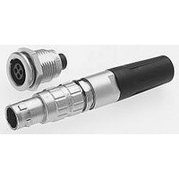
STRAIGHT PLUG
window in the one half bushing.
bushings.
connector housing
Fixed solder contacts 0.5 mm and 0.7 mm
1 - Insert wire into solder cup and solder.
.
on either side of the insulator.
.
appears through the
&
is aligned with the key way on the connector housing
into the
JBX Series
2 - Insert contact into the insulator until the clip is fully seated and cannot be removed.
per the torque spec on page 19.
17
Removable solder contacts from 0.9 mm to 2 mm
1 - Insert wire into solder cup and solder.
Window
Flats B
1 - Select the proper collet. (see page 19)
2 - Slide the protective boot
3 - If a shielded cable is used fold the braid back
1 - Select the proper crimping tool and
2 - Adjust the crimping tool based on wire
3 - Crimp the contacts
the collet
(see pg. 17).
over the collet.
locator. (see page 48)
size “AWG”. (See wire size and crimp
tool settings on the back of the locator)
contact into the insulator until the clip is
fully seated and cannot be removed.
.
over the cable. Strip end of cable
then insert the
the backnut
Flats A
and
Related parts for JBXED0G07FSSDPR
Image
Part Number
Description
Manufacturer
Datasheet
Request
R

Part Number:
Description:
CONN SEALING FOR WALL RCPT #22
Manufacturer:
Souriau Connection Technology
Part Number:
Description:
CONN SEALING FOR WALL RCPT #14
Manufacturer:
Souriau Connection Technology
Datasheet:

Part Number:
Description:
CONN RCPT SEALING CAP SIZE 10
Manufacturer:
Souriau Connection Technology
Datasheet:

Part Number:
Description:
CONN RCPT SEALING CAP SIZE 14
Manufacturer:
Souriau Connection Technology
Datasheet:

Part Number:
Description:
CONN STRAIN RELIEF 12POS
Manufacturer:
Souriau Connection Technology
Datasheet:

Part Number:
Description:
D38999 Series 3
Manufacturer:
Souriau Connection Technology
Datasheet: