LQH32MN2R2K23L Murata Electronics North America, LQH32MN2R2K23L Datasheet - Page 3
LQH32MN2R2K23L
Manufacturer Part Number
LQH32MN2R2K23L
Description
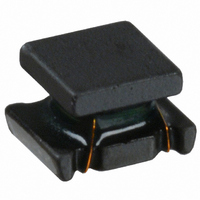
INDUCTOR 2.2UH 10% 370MA 1210
Manufacturer
Murata Electronics North America
Series
LQH32Mr
Datasheets
1.LQG15HS1N5S02D.pdf
(2 pages)
2.LQH32MN220J23L.pdf
(3 pages)
3.LQH32MN220J23L.pdf
(4 pages)
Specifications of LQH32MN2R2K23L
Inductance
2.2µH
Current
370mA
Tolerance
±10%
Dc Resistance (dcr)
800 mOhm Max
Q @ Freq
20 @ 1MHz
Self Resonant Freq
50MHz
Package / Case
1210 (3225 Metric)
Mounting Type
Surface Mount
Operating Temperature
-40°C ~ 85°C
Frequency - Test
1MHz
Applications
General Purpose
Lead Free Status / RoHS Status
Lead free / RoHS Compliant
Shielding
-
Current - Saturation
-
Current - Temperature Rise
-
Other names
490-2501-2
Available stocks
Company
Part Number
Manufacturer
Quantity
Price
Company:

Part Number:
LQH32MN2R2K23L
Manufacturer:
MURATA
Quantity:
24 000
Part Number:
LQH32MN2R2K23L
Manufacturer:
MURATA/村田
Quantity:
20 000


Inductor for Power Lines (Power Inductor)
(1) Land Pattern Dimensions
(3) PCB Warping
(3) Reworking with Soldering Iron
(2) Magnetic Coupling
3. Mounting Instructions
Preheating at 150 C for 1 minute is required. Do not
directly touch the ceramic element with the tip of the
soldering iron. The reworking soldering conditions are as
follows:
Large lands reduce Q of the mounted chip. Also, large
protruding land areas (bordered by lines having
dimensions 'c' and 'd' shown) cause floating and
electrode leaching.
Since some chip inductors (chip coils) are constructed
like an open magnetic circuit, narrow spacing between
inductors (coils) may cause magnetic coupling.
LQM, LQH66S and LQH_P series have a magnetically
shielded structure. The structure makes their coupling
coefficient smaller than that of conventional chip
inductors (chip coils).
PCB should be designed so that products are not
subjected to the mechanical stress caused by warping
the board.
Soldering and Mounting
except LQH3NP/44P/5BP
LQH3NP/44P/5BP
Soldering iron power output: 80W max.
Temperature of soldering iron tip: 350 C
Diameter of soldering iron end: 3.0mm max.
Soldering time: within 3 s
Products should be located in the sideways direction
(Length: a<b) to the mechanical stress.
The electrode part of the product should be located
like the picture to the mechanical stress.
Poor example
Poor example
Land
electrode
d
electrode
Continued on the following page.
Magnetic Coupling
Solder Resist
Good example
Good example
c
b
a
Related parts for LQH32MN2R2K23L
Image
Part Number
Description
Manufacturer
Datasheet
Request
R

Part Number:
Description:
INDUCTOR 1.0UH 20% 445MA 1210
Manufacturer:
Murata Electronics North America
Datasheet:
Part Number:
Description:
INDUCTOR 8.2UH 10% 225MA 1210
Manufacturer:
Murata Electronics North America
Datasheet:
Part Number:
Description:
INDUCTOR 22UH 5% 150MA 1210
Manufacturer:
Murata Electronics North America
Datasheet:
Part Number:
Description:
INDUCTOR 270UH 5% 65MA 1210
Manufacturer:
Murata Electronics North America
Datasheet:
Part Number:
Description:
INDUCTOR 10UH 5% 190MA 1210
Manufacturer:
Murata Electronics North America
Datasheet:
Part Number:
Description:
INDUCTOR 33UH 5% 115MA 1210
Manufacturer:
Murata Electronics North America
Datasheet:
Part Number:
Description:
INDUCTOR 150UH 5% 70MA 1210
Manufacturer:
Murata Electronics North America
Datasheet:
Part Number:
Description:
INDUCTOR 47UH 5% 100MA 1210
Manufacturer:
Murata Electronics North America
Datasheet:
Part Number:
Description:
INDUCTOR 560UH 5% 40MA 1210
Manufacturer:
Murata Electronics North America
Datasheet:
Part Number:
Description:
INDUCTOR 4.7UH 10% 270MA 1210
Manufacturer:
Murata Electronics North America
Datasheet:
Part Number:
Description:
INDUCTOR 330UH 5% 65MA 1210
Manufacturer:
Murata Electronics North America
Datasheet:
Part Number:
Description:
INDUCTOR 390UH 5% 50MA 1210
Manufacturer:
Murata Electronics North America
Datasheet:
Part Number:
Description:
INDUCTOR 6.8UH 10% 240MA 1210
Manufacturer:
Murata Electronics North America
Datasheet:
Part Number:
Description:
INDUCTOR 47UH 10% 100MA 1210
Manufacturer:
Murata Electronics North America
Datasheet:

Part Number:
Description:
BUZZER PIEZO 25VP-P SMD
Manufacturer:
Murata Electronics North America