VLF3014AT-220MR37 TDK Corporation, VLF3014AT-220MR37 Datasheet
VLF3014AT-220MR37
Manufacturer Part Number
VLF3014AT-220MR37
Description
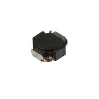
INDUCTOR POWER 22UH .37A SMD
Manufacturer
TDK Corporation
Series
VLFr
Datasheet
1.VLF3014AT-2R2M1R2.pdf
(2 pages)
Specifications of VLF3014AT-220MR37
Inductance
22µH
Tolerance
±20%
Current
370mA
Current - Temperature Rise
370mA
Shielding
Shielded
Dc Resistance (dcr)
1.2 Ohm Max
Package / Case
0.110" L x 0.102" W x 0.055" H (2.80mm x 2.60mm x 1.40mm)
Mounting Type
Surface Mount
Operating Temperature
-40°C ~ 105°C
Frequency - Test
100kHz
Applications
Power Line
Test Frequency
100 KHz
Maximum Dc Current
0.37 Amp
Maximum Dc Resistance
1.2 Ohms
Dimensions
2.8 mm W x 2.6 mm L x 1.4 mm H
Operating Temperature Range
- 40 C to + 105 C
Termination Style
SMD/SMT
Lead Free Status / RoHS Status
Lead free / RoHS Compliant
Q @ Freq
-
Self Resonant Freq
-
Current - Saturation
-
Lead Free Status / Rohs Status
Lead free / RoHS Compliant
Other names
445-4182-2


SMD Inductors(Coils)
For Power Line(Wound, Magnetic Shielded)
VLF Series VLF3014A
FEATURES
• Mount area: 2.6× 2.8mm
• Generic use for portable DC to DC converter line.
• High magnetic shield construction should actualize high resolu-
• Available for automatic mounting in tape and real package.
• The products contain no lead and also support lead-free
• It is a product conforming to RoHS directive.
APPLICATIONS
Power souce inductor for mobile devices such as mobile phones,
HDDs, and DSCs
ELECTRICAL CHARACTERISTICS
Part No.
VLF3014AT-1R0N1R8
VLF3014AT-2R2M1R2
VLF3014AT-3R3M1R0
VLF3014AT-4R7MR90
VLF3014AT-6R8MR72
VLF3014AT-100MR59
VLF3014AT-220MR37
∗1
∗2
∗3
∗4
• Operating temperature range: –40 to +105°C (Including self-temperature rise)
TYPICAL ELECTRICAL CHARACTERISTICS
INDUCTANCE vs. DC SUPERPOSITION CHARACTERISTICS
VLF3014AT-1R0N1R8
• Conformity to RoHS Directive: This means that, in conformity with EU Directive 2002/95/EC, lead, cadmium, mercury, hexavalent chromium, and specific
• All specifications are subject to change without notice.
bromine-based flame retardants, PBB and PBDE, have not been used, except for exempted applications.
Low profile: 1.4mm max. height
tion for EMC protection.
soldering.
Rated current based on inductance variation: Current when inductance decreases by 30% of the initial value due to direct current superimposed
characteristics
Rated current based on increasing product temperature: Current when temperature of the product reaches +40°C
Rated current based on inductance variation: Current when inductance decreases by 10% of the initial value due to direct current superimposed
characteristics
Inductance is at 1/2 Idc1 power distribution. The L vaule at 0A is higher than the guaranteed performance.
1.4
1.2
1.0
0.8
0.6
0.4
0.2
0.0
0.0
0.5
1.0
DC current ( A )
Inductance
[at 1/2 Idc1]
(µH)
1
2.2
3.3
4.7
6.8
10
22
1.5
2.0
∗4
±30
Inductance
tolerance(%)
±20
±20
±20
±20
±20
±20
2.5
3.0
Test frequency
(kHz)
100
100
100
100
100
100
100
SHAPES AND DIMENSIONS
RECOMMENDED PC BOARD PATTERN
VLF3014AT-2R2M1R2
2.8±0.2
DC
resistance(Ω)
max.
0.048
0.1
0.15
0.2
0.31
0.46
1.20
3.0
2.5
2.0
1.5
1.0
0.5
0.0
2.1
3.4
0.0
typ.
0.042
0.091
0.13
0.17
0.27
0.4
1
Dimensions in mm
0.5
Rated current(A)
Based on
inductance change
Idc1 max.
2.5
1.7
1.3
1.2
1
0.8
0.52
1.4max.
DC current ( A )
Dimensions in mm
∗1
1.0
002-04 / 20080821 / e531_vlf3014a.fm
Conformity to RoHS Directive
Based on
temperature
rise Idc2 typ.
1.8
1.2
1
0.9
0.72
0.59
0.37
1.5
∗2
Based on
inductance
change Idc3 typ.
2.5
1.6
1.1
0.8
0.78
0.65
0.43
2.0
(1/2)
∗3
Related parts for VLF3014AT-220MR37
Image
Part Number
Description
Manufacturer
Datasheet
Request
R

Part Number:
Description:
INDUCTOR POWER 4.7UH .9A SMD
Manufacturer:
TDK Corporation
Datasheet:

Part Number:
Description:
INDUCTOR POWER 2.2UH 1.2A SMD
Manufacturer:
TDK Corporation
Datasheet:

Part Number:
Description:
INDUCTOR POWER 3.3UH 1.0A SMD
Manufacturer:
TDK Corporation
Datasheet:

Part Number:
Description:
INDUCTOR POWER 6.8UH .72A SMD
Manufacturer:
TDK Corporation
Datasheet:
Part Number:
Description:
INDUCTOR POWER 10UH .59A SMD
Manufacturer:
TDK Corporation
Datasheet:

Part Number:
Description:
TDK DC to DC Converters, DC to AC Inverters
Manufacturer:
TDK Corporation
Datasheet:
Part Number:
Description:
TDK DC to DC Converters, DC to AC Inverters
Manufacturer:
TDK Corporation
Datasheet:
VLF3014AT-220MR37 Summary of contents
Page 1
... VLF3014AT-4R7MR90 4.7 VLF3014AT-6R8MR72 6.8 VLF3014AT-100MR59 10 VLF3014AT-220MR37 22 ∗1 Rated current based on inductance variation: Current when inductance decreases by 30% of the initial value due to direct current superimposed characteristics ∗2 Rated current based on increasing product temperature: Current when temperature of the product reaches +40°C ∗3 ...
Page 2
... DC current ( A ) VLF3014AT-6R8MR72 0.0 0.2 0.4 0.6 0.8 DC current ( A ) VLF3014AT-220MR37 0.0 0.1 0.2 0.3 0.4 DC current ( A ) TEST CIRCUIT C=20,000µF A L=0. Sample 1: LCR meter 4285A f=100kHz 2: DC constant current • All specifications are subject to change without notice. ...