VLF4014ST-3R3M1R6 TDK Corporation, VLF4014ST-3R3M1R6 Datasheet
VLF4014ST-3R3M1R6
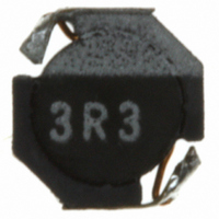
Manufacturer Part Number
VLF4014ST-3R3M1R6
Description
INDUCTOR POWER 3.3UH 1.6A SMD
Manufacturer
TDK Corporation
Series
VLFr
Datasheets
1.VLF4014AT-100MR90.pdf
(1 pages)
2.VLF4014ST-6R8M1R2.pdf
(2 pages)
3.VLF4014ST-100M1R0.pdf
(13 pages)
Specifications of VLF4014ST-3R3M1R6
Inductance
3.3µH
Tolerance
±20%
Current
1.6A
Current - Temperature Rise
1.6A
Shielding
Shielded
Dc Resistance (dcr)
107 mOhm Max
Package / Case
0.150" L x 0.142" W x 0.055" H (3.80mm x 3.60mm x 1.40mm)
Mounting Type
Surface Mount
Operating Temperature
-40°C ~ 105°C
Frequency - Test
1MHz
Applications
Power Line
Test Frequency
1 MHz
Maximum Dc Current
1.6 Amps
Maximum Dc Resistance
0.107 Ohms
Dimensions
3.8 mm W x 3.6 mm L x 1.4 mm H
Operating Temperature Range
- 40 C to + 105 C
Termination Style
SMD/SMT
Lead Free Status / RoHS Status
Lead free / RoHS Compliant
Q @ Freq
-
Self Resonant Freq
-
Current - Saturation
-
Lead Free Status / Rohs Status
Lead free / RoHS Compliant
Other names
445-4221-2


SMD Inductors(Coils)
For Power Line(Wound, Magnetic Shielded)
VLF Series VLF4014S
FEATURES
• Mount area: 3.6× 3.8mm
• Generic use for portable DC to DC converter line.
• High magnetic shield construction should actualize high resolu-
• Available for automatic mounting in tape and real package.
• The products contain no lead and also support lead-free
• It is a product conforming to RoHS directive.
APPLICATIONS
Power souce inductor for mobile devices such as mobile phones,
HDDs, and DSCs
ELECTRICAL CHARACTERISTICS
Part No.
VLF4014ST-1R0N2R3
VLF4014ST-2R2M1R9
VLF4014ST-3R3M1R6
VLF4014ST-4R7M1R4
VLF4014ST-6R8M1R2
VLF4014ST-100M1R0
∗
• Operating temperature range: –40 to +105°C (Including self-temperature rise)
TYPICAL ELECTRICAL CHARACTERISTICS
INDUCTANCE vs. DC SUPERPOSITION CHARACTERISTICS
VLF4014ST-1R0N2R3
• Conformity to RoHS Directive: This means that, in conformity with EU Directive 2002/95/EC, lead, cadmium, mercury, hexavalent chromium, and specific
• All specifications are subject to change without notice.
Rated current: Value obtained when current flows and the temperature has risen to 40°C or when DC current flows and the nominal value of inductance
has fallen by 30%, whichever is smaller.
bromine-based flame retardants, PBB and PBDE, have not been used, except for exempted applications.
Low profile: 1.4mm max. height
tion for EMC protection.
soldering.
2.0
1.5
1.0
0.5
0.0
0.0
0.5
1.0
DC current ( A )
1.5
Inductance
(µH)
1
2.2
3.3
4.7
6.8
10
2.0
2.5
±30
±20
±20
Inductance
tolerance(%)
±20
±20
±20
3.0
3.5
Test frequency
(MHz)
1
1
1
1
1
1
SHAPES AND DIMENSIONS
RECOMMENDED PC BOARD PATTERN
VLF4014ST-2R2M1R9
3.8±0.2
DC resistance(Ω)
max.
0.049
0.072
0.107
0.14
0.19
0.26
3.0
2.0
1.0
0.0
0.0 0.2 0.4 0.6 0.8 1.0 1.2 1.4 1.6 1.8 2.0 2.2 2.4
2.9
4.7
typ.
0.041
0.06
0.089
0.11
0.16
0.22
Dimensions in mm
Dimensions in mm
Rated current(A)
Based on inductance
change max.
2.7
2
1.7
1.4
1.2
1
DC current ( A )
1.4max.
002-04 / 20080821 / e531_vlf4014s.fm
Conformity to RoHS Directive
∗
Based on temperature
rise typ.
2.3
1.9
1.6
1.4
1.2
1
(1/2)
Related parts for VLF4014ST-3R3M1R6
Image
Part Number
Description
Manufacturer
Datasheet
Request
R

Part Number:
Description:
INDUCTOR POWER 4.7UH 1.4A SMD
Manufacturer:
TDK Corporation
Datasheet:

Part Number:
Description:
INDUCTOR POWER 6.8UH 1.2A SMD
Manufacturer:
TDK Corporation
Datasheet:

Part Number:
Description:
INDUCTOR POWER 10UH 1.0A SMD
Manufacturer:
TDK Corporation
Datasheet:

Part Number:
Description:
INDUCTOR POWER 2.2UH 1.9A SMD
Manufacturer:
TDK Corporation
Datasheet:

Part Number:
Description:
INDUCTOR POWER 1.0UH 2.3A SMD
Manufacturer:
TDK Corporation
Datasheet:

Part Number:
Description:
TDK DC to DC Converters, DC to AC Inverters
Manufacturer:
TDK Corporation
Datasheet:
Part Number:
Description:
TDK DC to DC Converters, DC to AC Inverters
Manufacturer:
TDK Corporation
Datasheet:
VLF4014ST-3R3M1R6 Summary of contents
Page 1
... ELECTRICAL CHARACTERISTICS Inductance Part No. (µH) VLF4014ST-1R0N2R3 1 ±30 VLF4014ST-2R2M1R9 2.2 ±20 VLF4014ST-3R3M1R6 3.3 ±20 VLF4014ST-4R7M1R4 4.7 VLF4014ST-6R8M1R2 6.8 VLF4014ST-100M1R0 10 ∗ Rated current: Value obtained when current flows and the temperature has risen to 40°C or when DC current flows and the nominal value of inductance has fallen by 30%, whichever is smaller. • ...
Page 2
... TYPICAL ELECTRICAL CHARACTERISTICS INDUCTANCE vs. DC SUPERPOSITION CHARACTERISTICS VLF4014ST-3R3M1R6 4.0 3.0 2.0 1.0 0.0 0.0 0.2 0.4 0.6 0.8 1.0 1.2 1.4 1.6 1.8 2.0 2.2 DC current ( A ) VLF4014ST-6R8M1R2 8.0 6.0 4.0 2.0 0.0 0.0 0.2 0.4 0.6 0.8 1.0 1.2 DC current ( A ) TEST CIRCUIT C=20,000µ ...