VLF10045T-221MR90 TDK Corporation, VLF10045T-221MR90 Datasheet
VLF10045T-221MR90
Manufacturer Part Number
VLF10045T-221MR90
Description
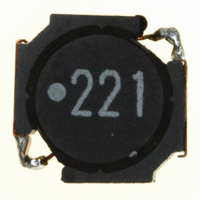
INDUCTOR POWER 220UH .90A SMD
Manufacturer
TDK Corporation
Series
VLFr
Datasheet
1.VLF10045T-1R0N100.pdf
(1 pages)
Specifications of VLF10045T-221MR90
Inductance
220µH
Tolerance
±20%
Current
900mA
Current - Temperature Rise
1A
Shielding
Shielded
Dc Resistance (dcr)
499 mOhm Max
Package / Case
0.394" L x 0.382" W x 0.177" H (10.00mm x 9.70mm x 4.50mm)
Mounting Type
Surface Mount
Operating Temperature
-40°C ~ 105°C
Frequency - Test
100kHz
Applications
Power Line
Test Frequency
100 KHz
Maximum Dc Current
0.9 Amp
Maximum Dc Resistance
499 mOhms
Dimensions
10 mm W x 9.7 mm L x 4.5 mm H
Operating Temperature Range
- 40 C to + 105 C
Termination Style
SMD/SMT
Lead Free Status / RoHS Status
Lead free / RoHS Compliant
Q @ Freq
-
Self Resonant Freq
-
Current - Saturation
-
Lead Free Status / Rohs Status
Lead free / RoHS Compliant
Other names
445-3586-2
Available stocks
Company
Part Number
Manufacturer
Quantity
Price
Company:

Part Number:
VLF10045T-221MR90
Manufacturer:
TDK
Quantity:
12 000
SMD Inductors(Coils)
For Power Line(Wound, Magnetic Shielded)
VLF Series VLF10045
FEATURES
• Mount area: 9.7× 10.0mm
• Compare to SLF10145(TDK conventional product) type
• Generic use for DC to DC converter line.
• High magnetic shield construction should actualize high resolu-
• Available for automatic mounting in tape and real package.
• The products contain no lead and also support lead-free
• It is a product conforming to RoHS directive.
APPLICATIONS
Note book computers, amusement equipment, DVD players,
VRMs, plasma displays, etc.
ELECTRICAL CHARACTERISTICS
Part No.
VLF10045T-1R0N100
VLF10045T-1R5N9R0
VLF10045T-2R2N7R4
VLF10045T-3R3N6R9
VLF10045T-4R7N6R1
VLF10045T-6R8N5R1
VLF10045T-100M4R3
VLF10045T-150M3R5
VLF10045T-220M2R8
VLF10045T-330M2R3
VLF10045T-470M1R9
VLF10045T-680M1R6
VLF10045T-101M1R3
VLF10045T-151M1R1
VLF10045T-221MR90
VLF10045T-331MR70
∗
• Operating temperature range: –40 to +105°C (Including self-temperature rise)
• Conformity to RoHS Directive: This means that, in conformity with EU Directive 2002/95/EC, lead, cadmium, mercury, hexavalent chromium, and specific
• All specifications are subject to change without notice.
Rated current: Value obtained when current flows and the temperature has risen to 40°C or when DC current flows and the nominal value of inductance
has fallen by 30%, whichever is smaller.
bromine-based flame retardants, PBB and PBDE, have not been used, except for exempted applications.
Low profile: 4.5mm max. height
Low loss and large current capability design
DC resistance: 0.89× SLF10145
Rated DC current: 1.47× SLF10145
tion for EMC protection.
soldering.
Inductance
(µH)
1.0
1.5
2.2
3.3
4.7
6.8
10
15
22
33
47
68
100
150
220
330
±30
±30
±20
±20
Inductance
tolerance(%)
±30
±30
±30
±30
±20
±20
±20
±20
±20
±20
±20
±20
Test frequency
(kHz)
100
100
100
100
100
100
100
100
100
100
100
100
100
100
100
100
SHAPES AND DIMENSIONS
RECOMMENDED PC BOARD PATTERN
DC resistance(mΩ)
max.
5.5
6.8
10.2
11.6
15
21.4
29
43
57
81
112
182
250
352
499
829
10.0±0.4
10.7
7.3
typ.
4.6
5.7
8.5
9.7
12.5
17.8
25.0
37.3
49.5
70.1
97.6
158
217
306
434
721
Rated current(A)
Based on inductance
change max.
13.5
11.1
9.1
7.5
6.3
5.2
4.3
3.5
2.8
2.3
1.9
1.6
1.3
1.1
0.9
0.7
Dimensions in mm
Dimensions in mm
002-02 / 20080629 / e531_vlf10045.fm
Conformity to RoHS Directive
4.5max.
∗
Based on temperature
rise typ.
10
9
7.4
6.9
6.1
5.1
4.3
3.5
3.0
2.6
2.2
1.7
1.4
1.2
1.0
0.8
(1/1)
Related parts for VLF10045T-221MR90
Image
Part Number
Description
Manufacturer
Datasheet
Request
R

Part Number:
Description:
INDUCTOR POWER 10UH 4.3A SMD
Manufacturer:
TDK Corporation
Datasheet:

Part Number:
Description:
INDUCTOR POWER 1.0UH 10.0A SMD
Manufacturer:
TDK Corporation
Datasheet:

Part Number:
Description:
INDUCTOR POWER 47UH 1.9A SMD
Manufacturer:
TDK Corporation
Datasheet:

Part Number:
Description:
INDUCTOR POWER 15UH 3.5A SMD
Manufacturer:
TDK Corporation
Datasheet:

Part Number:
Description:
INDUCTOR POWER 2.2UH 7.4A SMD
Manufacturer:
TDK Corporation
Datasheet:

Part Number:
Description:
INDUCTOR POWER 4.7UH 6.1A SMD
Manufacturer:
TDK Corporation
Datasheet:

Part Number:
Description:
INDUCTOR POWER 6.8UH 5.1A SMD
Manufacturer:
TDK Corporation
Datasheet:

Part Number:
Description:
INDUCTOR POWER 100UH 1.3A SMD
Manufacturer:
TDK Corporation
Datasheet:

Part Number:
Description:
INDUCTOR POWER 150UH 1.1A SMD
Manufacturer:
TDK Corporation
Datasheet:

Part Number:
Description:
INDUCTOR POWER 1.5UH 9A SMD
Manufacturer:
TDK Corporation
Datasheet:
