65EET Cooper/Bussmann, 65EET Datasheet - Page 2
65EET
Manufacturer Part Number
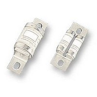
65EET
Description
FUSE 65A 660V TYPE T
Manufacturer
Cooper/Bussmann
Series
EETr
Datasheet
1.NO._140.pdf
(2 pages)
Specifications of 65EET
Voltage - Rated
690VAC
Current
65A
Package / Case
Bolt Mount
Size / Dimension
3.701" L x 1.457" W x 0.748" H (94.00mm x 37.00mm x 19.00mm)
Mounting Type
Bolt Mount
Rohs Compliant
YES
Lead Free Status / RoHS Status
Lead free / RoHS Compliant
Operating Temperature
-
Color
-
Fuse Type
-
Lead Free Status / RoHS Status
Lead free / RoHS Compliant


British Style BS 88
690V
Total Clearing I
The total clearing I
at power factor of 15% are given in the
electrical characteristics. For other volt-
ages, the clearing I
plying by correction factor, K , given as
a function of applied working voltage,
E
Dimensions
Electrical Characteristics
1.6
1.4
1.2
1.0
0.8
0.6
0.4
0.2
Fig. 1: CT
The only controlled copy of this BIF document is the electronic read-only version located on the Bussmann Network Drive. All other copies of this document are by definition uncontrolled.
This bulletin is intended to clearly present comprehensive product data and provide technical information that will help the end user with design applications. Bussmann reserves the right,
without notice, to change design or construction of any products and to discontinue or limit distribution of any products. Bussmann also reserves the right to change or update, without
notice, any technical information contained in this bulletin. Once a product has been selected, it should be tested by the user in all possible applications.
7-18-01
8.7
g
200
, (RMS).
1) CT, ET, EET, FE, FEE, MT, MMT
2) FM, FMM
1)
6.4
5.5
K
2)
300
54.8
400
SB01191
4
8.7
64.3
6-700A
2
2
2
t at rated voltage and
500
t is found by multi-
t
74.6
600 660
13.5
Fig. 4: FM, MT
E
g
25.4
38.1
10.3
50
41
Arc Voltage
This curve gives the peak arc voltage,
U
during its operation as a function of the
applied working voltage, E
power factor of 15%.
1500
1000
A
500
L
, which may appear across the fuse
1) CT
2) ET, FE, EET, FEE, FM, FMM
113
U
L
Fig. 2: ET, FE
9.7
200
400
7.1
48
17.1
19.1
1)
2)
12.7
600 660
63.5
g
, (RMS) at a
77
E
g
14
Fig. 5: FMM, MMT
25.4
38
Power Losses
Watts loss at rated current is given in
the electrical characteristics. The curve
allows the calculation of the power
losses at load currents lower than the
rated current. The correction factor, K
is given as a function of the RMS load
current, I
1.0
0.8
0.6
0.5
0.4
0.3
0.2
0.1
10.3
50
30 40 50
K
83
p
A
b
113
, in % of the rated current .
60
Fig. 3: EET, FEE
11.9
Dimensions in mm.
1mm = 0.0394∑
Type
FM
FMM
MT
MMT
70
Bussmann
80 90 100%
31.8
37
Dimension
BIF Doc #720024
80-85
80-85
“A”
I
85
85
b
1∑ = 25.4mm
8.7
®
46
Page 2 of 2
19
Form No.
70
94
p
®
,
Related parts for 65EET
Image
Part Number
Description
Manufacturer
Datasheet
Request
R

Part Number:
Description:
Manufacturer:
Cooper/Bussmann
Datasheet:
Part Number:
Description:
Manufacturer:
Cooper/Bussmann
Datasheet: