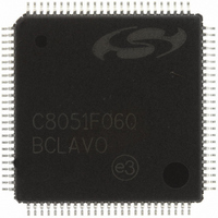
C8051F060-GQ Silicon Laboratories Inc, C8051F060-GQ Datasheet - Page 10

C8051F060-GQ
Manufacturer Part Number
C8051F060-GQ
Description
IC 8051 MCU 64K FLASH 100TQFP
Manufacturer
Silicon Laboratories Inc
Series
C8051F06xr
Specifications of C8051F060-GQ
Program Memory Type
FLASH
Program Memory Size
64KB (64K x 8)
Package / Case
100-TQFP, 100-VQFP
Core Processor
8051
Core Size
8-Bit
Speed
25MHz
Connectivity
CAN, EBI/EMI, SMBus (2-Wire/I²C), SPI, UART/USART
Peripherals
Brown-out Detect/Reset, POR, PWM, Temp Sensor, WDT
Number Of I /o
59
Ram Size
4.25K x 8
Voltage - Supply (vcc/vdd)
2.7 V ~ 3.6 V
Data Converters
A/D 2x16b, 8x10b; D/A 2x12b
Oscillator Type
Internal
Operating Temperature
-40°C ~ 85°C
Processor Series
C8051F0x
Core
8051
Data Bus Width
8 bit
Data Ram Size
4.25 KB
Interface Type
CAN/I2C/SMBus/SPI/UART
Maximum Clock Frequency
25 MHz
Number Of Programmable I/os
59
Number Of Timers
5
Operating Supply Voltage
2.7 V to 3.6 V
Maximum Operating Temperature
+ 85 C
Mounting Style
SMD/SMT
3rd Party Development Tools
PK51, CA51, A51, ULINK2
Development Tools By Supplier
C8051F060DK
Minimum Operating Temperature
- 40 C
On-chip Adc
8-ch x 10-bit
On-chip Dac
2-ch x 12-bit
No. Of I/o's
59
Ram Memory Size
4352Byte
Cpu Speed
25MHz
No. Of Timers
5
Rohs Compliant
Yes
Lead Free Status / RoHS Status
Lead free / RoHS Compliant
For Use With
336-1214 - DEV KIT FOR F060/F062/F063
Eeprom Size
-
Lead Free Status / Rohs Status
Lead free / RoHS Compliant
Other names
336-1213
Available stocks
Company
Part Number
Manufacturer
Quantity
Price
Company:
Part Number:
C8051F060-GQ
Manufacturer:
VISHAY
Quantity:
3 000
Company:
Part Number:
C8051F060-GQ
Manufacturer:
Silicon Laboratories Inc
Quantity:
10 000
Company:
Part Number:
C8051F060-GQR
Manufacturer:
Silicon Laboratories Inc
Quantity:
10 000
Company:
Part Number:
C8051F060-GQR.
Manufacturer:
SILICON
Quantity:
15 000
C8051F060/1/2/3/4/5/6/7
6. Direct Memory Access Interface (DMA0) ............................................................. 75
7. 10-Bit ADC (ADC2, C8051F060/1/2/3).................................................................... 87
10
Figure 5.17. ADC1L: ADC1 Data Word LSB Register.............................................. 65
Figure 5.18. ADC1 Data Word Example................................................................... 65
Figure 5.19. Calibration Coefficient Locations.......................................................... 66
Figure 5.20. Offset and Gain Register Mapping ....................................................... 67
Figure 5.21. Offset and Gain Calibration Block Diagram.......................................... 67
Figure 5.22. ADC0CPT: ADC Calibration Pointer Register ...................................... 68
Figure 5.23. ADC0CCF: ADC Calibration Coefficient Register ................................ 68
Figure 5.24. ADC0GTH: ADC0 Greater-Than Data High Byte Register .................. 69
Figure 5.25. ADC0GTL: ADC0 Greater-Than Data Low Byte Register.................... 69
Figure 5.26. ADC0LTH: ADC0 Less-Than Data High Byte Register........................ 70
Figure 5.27. ADC0LTL: ADC0 Less-Than Data Low Byte Register ......................... 70
Figure 5.28. 16-Bit ADC0 Window Interrupt Example: Single-Ended Data .............. 71
Figure 5.29. 16-Bit ADC0 Window Interrupt Example: Differential Data .................. 72
Figure 6.1. DMA0 Block Diagram............................................................................. 75
Figure 6.2. DMA Mode 0 Operation ......................................................................... 77
Figure 6.3. DMA Mode 1 Operation ......................................................................... 78
Figure 6.4. DMA0CN: DMA0 Control Register ......................................................... 80
Figure 6.5. DMA0CF: DMA0 Configuration Register................................................ 81
Figure 6.6. DMA0IPT: DMA0 Instruction Write Address Register ............................ 82
Figure 6.7. DMA0IDT: DMA0 Instruction Write Data Register ................................. 82
Figure 6.8. DMA0BND: DMA0 Instruction Boundary Register ................................. 83
Figure 6.9. DMA0ISW: DMA0 Instruction Status Register ....................................... 83
Figure 6.10. DMA0DAH: DMA0 Data Address Beginning MSB Register................. 84
Figure 6.11. DMA0DAL: DMA0 Data Address Beginning LSB Register .................. 84
Figure 6.12. DMA0DSH: DMA0 Data Address Pointer MSB Register ..................... 84
Figure 6.13. DMA0DSL: DMA0 Data Address Pointer LSB Register ....................... 84
Figure 6.14. DMA0CTH: DMA0 Repeat Counter Limit MSB Register...................... 85
Figure 6.15. DMA0CTL: DMA0 Repeat Counter Limit LSB Register ....................... 85
Figure 6.16. DMA0CSH: DMA0 Repeat Counter MSB Register .............................. 85
Figure 6.17. DMA0CSL: DMA0 Repeat Counter LSB Register................................ 85
Figure 7.1. ADC2 Functional Block Diagram............................................................ 87
Figure 7.2. Temperature Sensor Transfer Function ................................................. 89
Figure 7.3. 10-Bit ADC Track and Conversion Example Timing .............................. 90
Figure 7.4. ADC2 Equivalent Input Circuits.............................................................. 91
Figure 7.5. AMX2CF: AMUX2 Configuration Register ............................................. 92
Figure 7.6. AMX2SL: AMUX2 Channel Select Register........................................... 93
Figure 7.7. ADC2CF: ADC2 Configuration Register ................................................ 94
Figure 7.8. ADC2H: ADC2 Data Word MSB Register .............................................. 95
Figure 7.9. ADC2L: ADC2 Data Word LSB Register................................................ 95
Figure 7.10. ADC2CN: ADC2 Control Register ........................................................ 96
Figure 7.11. ADC2GTH: ADC2 Greater-Than Data High Byte Register .................. 97
Figure 7.12. ADC2GTL: ADC2 Greater-Than Data Low Byte Register.................... 97
Figure 7.13. ADC2LTH: ADC2 Less-Than Data High Byte Register........................ 98
Rev. 1.2


