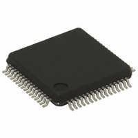
STR752FR1T7 STMicroelectronics, STR752FR1T7 Datasheet - Page 60

STR752FR1T7
Manufacturer Part Number
STR752FR1T7
Description
MCU 32BIT 128KB FLASH 64LQFP
Manufacturer
STMicroelectronics
Series
STR7r
Datasheet
1.STR750FV0T6.pdf
(84 pages)
Specifications of STR752FR1T7
Core Processor
ARM7
Core Size
32-Bit
Speed
60MHz
Connectivity
CAN, I²C, SPI, SSI, SSP, UART/USART
Peripherals
DMA, PWM, WDT
Number Of I /o
38
Program Memory Size
128KB (128K x 8)
Program Memory Type
FLASH
Ram Size
16K x 8
Voltage - Supply (vcc/vdd)
3 V ~ 5.5 V
Data Converters
A/D 11x10b
Oscillator Type
Internal
Operating Temperature
-40°C ~ 105°C
Package / Case
64-LQFP
Processor Series
STR752x
Core
ARM7TDMI
Data Bus Width
32 bit
Data Ram Size
16 KB
Interface Type
CAN, I2C, SPI, SSI, SSP, USB
Maximum Clock Frequency
60 MHz
Number Of Programmable I/os
38
Number Of Timers
6
Maximum Operating Temperature
+ 85 C
Mounting Style
SMD/SMT
3rd Party Development Tools
EWARM, EWARM-BL, KSDK-STR750-PLUS, MCBSTR750, MCBSTR750U, MCBSTR750UME, MDK-ARM, RL-ARM, ULINK2
Development Tools By Supplier
STR750-MCKIT, STR750-SK/HIT, STR750-SK/IAR, STR750-SK/KEIL, STR750-SK/RAIS, STR750-EVAL, STX-PRO/RAIS, STX-RLINK, STR79-RVDK/CPP, STR79-RVDK, STR79-RVDK/UPG
Minimum Operating Temperature
- 40 C
On-chip Adc
10 bit, 11 Channel
For Use With
MCBSTR750UME - BOARD EVAL MCBSTR750 + ULINK-MEMCBSTR750U - BOARD EVAL MCBSTR750 + ULINK2497-5754 - KIT STARTER IAR STR750497-5753 - KIT STARTER KEIL FOR STR7/STR9497-5752 - KIT STARTER IAR FOR STR7/STR9497-5748 - BOARD EVALUATION FOR STR750XF
Lead Free Status / RoHS Status
Lead free / RoHS Compliant
Eeprom Size
-
Lead Free Status / Rohs Status
Details
Available stocks
Company
Part Number
Manufacturer
Quantity
Price
Company:
Part Number:
STR752FR1T7
Manufacturer:
STMicroelectronics
Quantity:
10 000
Electrical parameters
6.3.9
60/84
TB and TIM timer characteristics
Subject to general operating conditions for V
specified.
Refer to
input/output alternate function characteristics (output compare, input capture, external clock,
PWM output...).
Table 36. TB and TIM timers
1. Take into account the frequency limitation due to the I/O speed capability when outputting the PWM to I/O
t
MAX_COUNT
t
t
COUNTER
Symbol
w(ICAP)in
t
Res
res(TIM)
pin, described in
f
EXT
TIM
Section 6.3.8: I/O port pin characteristics on page 54
Input capture
pulse time
Timer
resolution
time
Timer
external clock
frequency on
TI1 or TI2
Timer
resolution
16-bit
Counter clock
period when
internal clock
is selected
(16-bit
Prescaler)
Maximum
Possible
Count
Parameter
(1)
: Output speed on page
TIM0,1,2
TB
TIM0,1,2
TIM0,1,2
TB
TIM0,1,2
TB
TIM0,1,2
f
f
60 MHz
f
f
60MHz
f
f
60 MHz
f
60 MHz
f
60 MHz
f
60 MHz
f
60 MHz
CK_TIM(MAX)
CK_TIM
CK_TIM(MAX)
CK_TIM
CK_TIM(MAX)
CK_TIM
CK_TIM
CK_TIM
CK_TIM
CK_TIM
Conditions
57.
STR750Fxx STR751Fxx STR752Fxx STR755Fxx
= f
= f
= f
= f
= f
= f
= f
CK_SYS
CK_SYS
CK_SYS
CK_SYS
CK_SYS
CK_SYS
CK_SYS
DD_IO
= f
= f
= f
CK_SYS
CK_SYS
CK_SYS
, f
=
=
=
=
=
=
=
CK_SYS
0.0166
0.0166
16.6
16.6
Min
2
1
1
0
0
1
1
, and T
(1)
(1)
for more details on the
Typ
A
unless otherwise
65536x65536 t
65536x65536 t
f
CK_TIM
65536
65536
71.58
71.58
1092
1092
Max
15
16
/4
t
t
t
t
t
CK_TIM
CK_TIM
CK_TIM
CK_TIM
CK_TIM
CK_TIM
CK_TIM
MHz
MHz
Unit
ns
ns
bit
µs
µs
s
s


