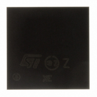
STR710RZH6 STMicroelectronics, STR710RZH6 Datasheet - Page 76

STR710RZH6
Manufacturer Part Number
STR710RZH6
Description
MCU ARM7 32BIT 64-LFBGA
Manufacturer
STMicroelectronics
Series
STR7r
Datasheet
1.RLINK-ST.pdf
(78 pages)
Specifications of STR710RZH6
Core Processor
ARM7
Core Size
32-Bit
Speed
66MHz
Connectivity
CAN, EBI/EMI, HDLC, I²C, SmartCard, SPI, UART/USART, USB
Peripherals
PWM, WDT
Number Of I /o
48
Program Memory Type
ROMless
Ram Size
64K x 8
Voltage - Supply (vcc/vdd)
3 V ~ 3.6 V
Data Converters
A/D 4x12b
Oscillator Type
Internal
Operating Temperature
-40°C ~ 85°C
Package / Case
64-LFBGA
Processor Series
STR710x
Core
ARM7TDMI
Data Bus Width
32 bit
Data Ram Size
64 KB
Interface Type
CAN, EMI, USB
Maximum Clock Frequency
66 MHz
Number Of Programmable I/os
48
Number Of Timers
4
Maximum Operating Temperature
+ 85 C
Mounting Style
SMD/SMT
3rd Party Development Tools
EWARM, EWARM-BL, MCBSTR7, MDK-ARM, RL-ARM, ULINK2
Development Tools By Supplier
STX-PRO/RAIS, STX-RLINK, STR79-RVDK/CPP, STR79-RVDK, STR79-RVDK/UPG
Minimum Operating Temperature
- 40 C
On-chip Adc
12 bit, 4 Channel
For Use With
MCBSTR7UME - MCBSTR7 + ULINK-ME DEV KITMCBSTR7 - BOARD EVAL STM STR71X SERIES497-4516 - BOARD EVAL FOR STR71X SER MCU
Lead Free Status / RoHS Status
Lead free / RoHS Compliant
Eeprom Size
-
Program Memory Size
-
Lead Free Status / Rohs Status
Details
Available stocks
Company
Part Number
Manufacturer
Quantity
Price
Company:
Part Number:
STR710RZH6
Manufacturer:
STMicroelectronics
Quantity:
900
Company:
Part Number:
STR710RZH6
Manufacturer:
STMicroelectronics
Quantity:
10 000
Revision history
8
76/78
Revision history
Table 46.
17-Mar-2004
25-Jan-2005
05-Apr-2004
08-Apr-2004
15-Apr-2004
29-Oct-2004
19-Apr-2005
13-Oct-2005
7-Jul-2004
Date
Document revision history
Revision
2.1
2.2
1
2
3
4
5
6
7
First Release
Updated “Electrical parameters” on page 33
PDF hyperlinks corrected.
Corrected description of STDBY, V18, VSS18 V18BKP
VSSBKP pins
Added IDDrun typical data
Updated BSPI max. baudrate.
Updated “EMI - external memory interface” on page 56
Corrected Flash sector B1F0/F1 address in
map on page 30
Corrected
of 17. Added to TQPFP64 column: pin 7 BOOTEN, pin 17
V
Changed description of JTCK from ‘External pull-down
required’ to ‘External pull-up or pull down required’.
Changed “Product Preview” to “Preliminary Data” on page 1
and 3
Renamed ‘PU/PD’ column to ‘Reset state’ in
page 24
Added reference to STR7 Flash Programming Reference
Manual
Added STR715F devices and modified RAM size of STR71xF1
devices
Added BGA package in
Updated ordering information in
Added PLL duty cycle min and max. in
characteristics on page 44
Updated feature description on page 1
Update overview
Added OD/PP to P0.12 in
Changed name of WFI mode to WAIT mode
Changed Memory Map
and flash register changed to 36 bytes.
Added Power Consumption
Modified BGA144 F3, F5, F12 and G12 in
Update EMI Timing
Corrected STR712F Pinout. Pins 43/42 swapped.
33IO-PLL
Table 7 on page 24
Section 1.1
Table 26
Table
Section 5
Table 7
Changes
Table 15
and
6: Ext. Memory changed to 64 MB
LQFP64 TEST pin is 16 instead
Section
Figure 29
PLL electrical
7.
Table 3
Figure 6: Memory
Table 7 on
and
STR71xF
Table 4


