C8051T617-GM Silicon Laboratories Inc, C8051T617-GM Datasheet - Page 193
C8051T617-GM
Manufacturer Part Number
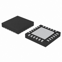
C8051T617-GM
Description
IC 8051 MCU 16K BYTE-PROG 24-QFN
Manufacturer
Silicon Laboratories Inc
Series
C8051T61xr
Specifications of C8051T617-GM
Core Processor
8051
Core Size
8-Bit
Speed
25MHz
Connectivity
SMBus (2-Wire/I²C), SPI, UART/USART
Peripherals
POR, PWM, WDT
Number Of I /o
21
Program Memory Size
16KB (16K x 8)
Program Memory Type
OTP
Ram Size
1.25K x 8
Voltage - Supply (vcc/vdd)
1.8 V ~ 3.6 V
Oscillator Type
Internal
Operating Temperature
-40°C ~ 85°C
Package / Case
24-QFN
Lead Free Status / RoHS Status
Lead free / RoHS Compliant
Eeprom Size
-
Data Converters
-
Other names
336-1438-5


26.3. Capture/Compare Modules
Each module can be configured to operate independently in one of six operation modes: edge-triggered
capture, software timer, high-speed output, frequency output, 8-bit pulse width modulator, or 16-bit pulse
width modulator. Each module has Special Function Registers (SFRs) associated with it in the CIP-51 sys-
tem controller. These registers are used to exchange data with a module and configure the module's mode
of operation. Table 26.2 summarizes the bit settings in the PCA0CPMn register used to select the PCA
capture/compare module’s operating mode. Setting the ECCFn bit in a PCA0CPMn register enables the
module's CCFn interrupt.
Operational Mode
Capture triggered by positive edge on CEXn
Capture triggered by negative edge on CEXn
Capture triggered by any transition on CEXn
Software Timer
High Speed Output
Frequency Output
8-Bit Pulse Width Modulator
16-Bit Pulse Width Modulator
Notes:
1. X = Don’t Care (no functional difference for individual module if 1 or 0).
2. A = Enable interrupts for this module (PCA interrupt triggered on CCFn set to 1).
3. B = When set to 0, the digital comparator is off. For high speed and frequency output modes, the associated
4. C = When set, a match event will cause the CCFn flag for the associated channel to be set.
pin will not toggle. In any of the PWM modes, this generates a 0% duty cycle (output = 0).
Table 26.2. PCA0CPM Bit Settings for PCA Capture/Compare Modules
Rev 1.0
C8051T610/1/2/3/4/5/6/7
Bit Number 7 6 5 4 3 2 1 0
X X 1 0 0 0 0 A
X X 0 1 0 0 0 A
X X 1 1 0 0 0 A
X B 0 0 1 0 0 A
X B 0 0 1 1 0 A
X B 0 0 0 1 1 A
0 B 0 0 C 0 1 A
1 B 0 0 C 0 1 A
PCA0CPMn
193
Related parts for C8051T617-GM
Image
Part Number
Description
Manufacturer
Datasheet
Request
R

Part Number:
Description:
SMD/C°/SINGLE-ENDED OUTPUT SILICON OSCILLATOR
Manufacturer:
Silicon Laboratories Inc
Part Number:
Description:
Manufacturer:
Silicon Laboratories Inc
Datasheet:
Part Number:
Description:
N/A N/A/SI4010 AES KEYFOB DEMO WITH LCD RX
Manufacturer:
Silicon Laboratories Inc
Datasheet:
Part Number:
Description:
N/A N/A/SI4010 SIMPLIFIED KEY FOB DEMO WITH LED RX
Manufacturer:
Silicon Laboratories Inc
Datasheet:
Part Number:
Description:
N/A/-40 TO 85 OC/EZLINK MODULE; F930/4432 HIGH BAND (REV E/B1)
Manufacturer:
Silicon Laboratories Inc
Part Number:
Description:
EZLink Module; F930/4432 Low Band (rev e/B1)
Manufacturer:
Silicon Laboratories Inc
Part Number:
Description:
I°/4460 10 DBM RADIO TEST CARD 434 MHZ
Manufacturer:
Silicon Laboratories Inc
Part Number:
Description:
I°/4461 14 DBM RADIO TEST CARD 868 MHZ
Manufacturer:
Silicon Laboratories Inc
Part Number:
Description:
I°/4463 20 DBM RFSWITCH RADIO TEST CARD 460 MHZ
Manufacturer:
Silicon Laboratories Inc
Part Number:
Description:
I°/4463 20 DBM RADIO TEST CARD 868 MHZ
Manufacturer:
Silicon Laboratories Inc
Part Number:
Description:
I°/4463 27 DBM RADIO TEST CARD 868 MHZ
Manufacturer:
Silicon Laboratories Inc
Part Number:
Description:
I°/4463 SKYWORKS 30 DBM RADIO TEST CARD 915 MHZ
Manufacturer:
Silicon Laboratories Inc
Part Number:
Description:
N/A N/A/-40 TO 85 OC/4463 RFMD 30 DBM RADIO TEST CARD 915 MHZ
Manufacturer:
Silicon Laboratories Inc
Part Number:
Description:
I°/4463 20 DBM RADIO TEST CARD 169 MHZ
Manufacturer:
Silicon Laboratories Inc