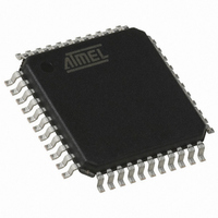
T89C51CC01UA-RLTIM Atmel, T89C51CC01UA-RLTIM Datasheet - Page 8

T89C51CC01UA-RLTIM
Manufacturer Part Number
T89C51CC01UA-RLTIM
Description
IC 8051 MCU FLASH 32K 44VQFP
Manufacturer
Atmel
Series
AT89C CANr
Datasheets
1.T89C51CC01CA-7CTIM.pdf
(167 pages)
2.T89C51CC01CA-7CTIM.pdf
(12 pages)
3.T89C51CC01CA-7CTIM.pdf
(32 pages)
4.T89C51CC01CA-7CTIM.pdf
(29 pages)
Specifications of T89C51CC01UA-RLTIM
Core Processor
8051
Core Size
8-Bit
Speed
40MHz
Connectivity
CAN, UART/USART
Peripherals
POR, PWM, WDT
Number Of I /o
32
Program Memory Size
32KB (32K x 8)
Program Memory Type
FLASH
Eeprom Size
2K x 8
Ram Size
1.25K x 8
Voltage - Supply (vcc/vdd)
3 V ~ 5.5 V
Data Converters
A/D 8x10b
Oscillator Type
External
Operating Temperature
-40°C ~ 85°C
Package / Case
44-TQFP, 44-VQFP
For Use With
AT89STK-06 - KIT DEMOBOARD 8051 MCU W/CAN
Lead Free Status / RoHS Status
Contains lead / RoHS non-compliant
Other names
T89C51CC01UARLTIM
Available stocks
Company
Part Number
Manufacturer
Quantity
Price
Physical Layer
CAN Controller
Initialization
8
T89C51CC01 CAN Bootloader
The CAN is used to transmit information has the following configuration:
•
•
•
Two ways are possible to initialize the CAN controller:
•
•
The selection between these two solutions is made with EB:
•
•
CANBT1:3 and EB can be modified by user through a set of API or with ISP commands.
The figure below describes the CAN controller flow.
Figure 4. CAN Controller Initialization
Standard Frame CAN format 2.0A (identifier 11-bit)
Frame: Data Frame
Baud rate: autobaud is performed by the bootloader
Use the software autobaud
Use the user configuration stored in the CANBT1, CANBT2 and CANBT3
EB = FFh: the autobaud is performed.
EB not equal to FFh: the CANBT1:2:3 are used.
Read CANBT1 Value
Read CANBT2 Value
Read CANBT3 Value
Configure the CAN
CANBTx = FFh
CAN Controller
Initialization
CAN Macro
CAN Error
EB = FFh
Controller
Initialized
x=(1,3)
No
No
No
Yes
Yes
Yes
Yes
Set the CAN Controller in
Autobaud Mode
Autobaud OK
No
4210E–CAN–03/08


