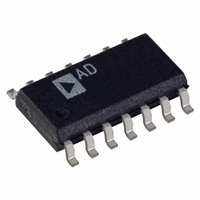
OP462GSZ Analog Devices Inc, OP462GSZ Datasheet - Page 15

OP462GSZ
Manufacturer Part Number
OP462GSZ
Description
IC OPAMP GP R-R 15MHZ LN 14SOIC
Manufacturer
Analog Devices Inc
Type
General Purpose Amplifierr
Datasheet
1.OP162GSZ.pdf
(20 pages)
Specifications of OP462GSZ
Slew Rate
13 V/µs
Amplifier Type
General Purpose
Number Of Circuits
4
Output Type
Rail-to-Rail
Gain Bandwidth Product
15MHz
Current - Input Bias
260nA
Voltage - Input Offset
25µV
Current - Supply
550µA
Current - Output / Channel
30mA
Voltage - Supply, Single/dual (±)
2.7 V ~ 12 V, ±1.35 V ~ 6 V
Operating Temperature
-40°C ~ 125°C
Mounting Type
Surface Mount
Package / Case
14-SOIC (3.9mm Width), 14-SOL
Op Amp Type
Low Power
No. Of Amplifiers
4
Bandwidth
15MHz
Supply Voltage Range
2.7V To 12V
Amplifier Case Style
SOIC
No. Of Pins
14
Rail/rail I/o Type
Rail to Rail Output
Number Of Elements
4
Unity Gain Bandwidth Product
15MHz
Common Mode Rejection Ratio
70dB
Input Offset Voltage
325uV
Input Bias Current
600nA
Single Supply Voltage (typ)
3/5/9V
Dual Supply Voltage (typ)
±3/±5V
Voltage Gain In Db
98.89dB
Power Supply Rejection Ratio
120dB
Power Supply Requirement
Single/Dual
Shut Down Feature
No
Single Supply Voltage (min)
2.7V
Single Supply Voltage (max)
12V
Dual Supply Voltage (min)
±1.35V
Dual Supply Voltage (max)
±6V
Technology
BiCOM
Operating Temp Range
-40C to 125C
Operating Temperature Classification
Automotive
Mounting
Surface Mount
Pin Count
14
Package Type
SOIC N
Lead Free Status / RoHS Status
Lead free / RoHS Compliant
-3db Bandwidth
-
Lead Free Status / Rohs Status
Compliant
Available stocks
Company
Part Number
Manufacturer
Quantity
Price
Part Number:
OP462GSZ
Manufacturer:
ADI/亚德诺
Quantity:
20 000
Part Number:
OP462GSZ-REEL
Manufacturer:
ADI/亚德诺
Quantity:
20 000
Part Number:
OP462GSZ-REEL7
Manufacturer:
ADI/亚德诺
Quantity:
20 000
The network operates in parallel with the load capacitor, C
and provides compensation for the added phase lag. The actual
values of the network resistor and capacitor are empirically
determined to minimize overshoot and maximize unity-gain
bandwidth. Table 6 shows a few sample snubber networks for
large load capacitors.
Table 6. Snubber Networks for Large Capacitive Loads
C
< 300 pF
500 pF
1 nF
10 nF
Higher load capacitance will reduce the unity-gain bandwidth
of the device. Figure 43 shows unity-gain bandwidth vs.
capacitive load. The snubber network does not provide any
increase in bandwidth, but it substantially reduces ringing and
overshoot, as shown between Figure 41 and Figure 42.
TOTAL HARMONIC DISTORTION AND CROSSTALK
The OPx62 device family offers low total harmonic distortion
making it an excellent choice for audio applications. Figure 44
shows a graph of THD plus noise figures at 0.001% for the
OP462.
LOAD
100
0%
90
10
10
Figure 42. A Photo of a Nice Square Wave at the Output
10pF
9
8
7
6
5
4
3
2
1
0
Figure 43. Unity-Gain Bandwidth vs. C
50mV
100pF
R
140 Ω
100 Ω
80 Ω
10 Ω
X
C
LOAD
V
A
C
R
WITH SNUBBER:
1nF
R
C
1 µ s
S
V
L
L
X
X
= 5V
= 1
= 300pF
= 10k Ω
= 140 Ω
= 10nF
LOAD
C
10 nF
10 nF
10 nF
47 nF
X
10nF
L
,
Rev. F | Page 15 of 20
Figure 45 shows the worst case crosstalk between two amplifiers
in the OP462. A 1 V rms signal is applied to one amplifier while
measuring the output of an adjacent amplifier. Both amplifiers
are configured for unity gain and supplied with ±2.5 V.
PCB LAYOUT CONSIDERATIONS
Because the OP162/OP262/OP462 can provide gains at high
frequency, careful attention to board layout and component
selection is recommended. As with any high speed application,
a good ground plane is essential to achieve the optimum
performance. This can significantly reduce the undesirable
effects of ground loops and I × R losses by providing a low
impedance reference point. Best results are obtained with a
multilayer board design with one layer assigned to ground
plane.
Use chip capacitors for supply bypassing, with one end of the
capacitor connected to the ground plane and the other end
connected within 1/8 inch of each power pin. An additional
large tantalum electrolytic capacitor (4.7 µF to 10 µF) should be
connected in parallel. This capacitor provides current for fast,
large-signal changes at the device’s output; therefore, it does not
need to be placed as close to the supply pins.
0.0001
0.010
0.001
–100
–110
–120
–130
–140
–40
–50
–60
–70
–80
–90
20
20
V
A
V
R
BANDWIDTH:
<10Hz TO 22kHz
A
V
R
V
S
IN
IN
S
V
L
V
L
= ±2.5V
= 1
= 10kΩ
= 1
= 10kΩ
= ±2.5V
= 1.0V rms
= 1.0V rms
(0dBV)
Figure 45. Crosstalk vs. Frequency
Figure 44. THD + N vs. Frequency
100
100
FREQUENCY (Hz)
FREQUENCY (Hz)
OP162/OP262/OP462
1k
1k
10k 20k
10k 20k


