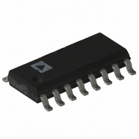
SMP04ESZ Analog Devices Inc, SMP04ESZ Datasheet

SMP04ESZ
Specifications of SMP04ESZ
Available stocks
Related parts for SMP04ESZ
SMP04ESZ Summary of contents
Page 1
...
Page 2
SMP04–SPECIFICATIONS ELECTRICAL CHARACTERISTICS specified in Absolute Maximum Ratings, unless otherwise noted.) Parameter Symbol Linearity Error Buffer Offset Voltage V Hold Step V Droop Rate 1 Output Source Current I 1 Output Sink Current I Output Voltage Range OVR LOGIC CHARACTERISTICS ...
Page 3
ABSOLUTE MAXIMUM RATINGS (T = +25 C unless otherwise noted DGND . . . . . . . . . . . . . . . . . . . . . . . . . . ...
Page 4
SMP04 WAFER TEST LIMITS (@ Parameter Buffer Offset Voltage Hold Step Droop Rate Output Source Current Output Sink Current Output Voltage Range LOGIC CHARACTERISTICS Logic Input High Voltage Logic Input Low Voltage Logic Input ...
Page 5
V = +12V +5V IN 1000 R = 10k L 100 10 0 –55 –35 – 105 125 TEMPERATURE – C Figure 1. Droop Rate vs. Temperature ...
Page 6
SMP04 +12V +5V IN – 10k L –2 –3 –4 –5 –55 –33 – 105 125 TEMPERATURE – C Figure 10. Offset Voltage ...
Page 7
GENERAL INFORMATION The SMP04 is a quad sample-and-hold with each track-and- hold having its own input, output, control, and on-chip hold capacitor. The combination of four high performance track-and- hold capacitors on a single chip greatly reduces board space and ...
Page 8
SMP04 FREQUENCY DOMAIN PERFORMANCE The SMP04 has been characterized in the frequency domain for those applications that require capture of dynamic signals. See Figure 16a for typical 86.1 kHz sample rate and an 8 kHz input signal. Typically, the SMP04 ...
Page 9
Sample-Mode Distortion Characteristics Although designed as a sample-and-hold, the SMP04 may be used as a straight buffer amplifier by configuring continu- ous sample mode. This is done by connecting the S/H control pin to a logic LOW. ...
Page 10
SMP04 APPLICATIONS MULTIPLEXED QUAD DAC (Figure 20) The SMP04 can be used to demultiplex a single DAC converter’s output into four separate analog outputs. The circuit is greatly simplified by using a voltage output DAC such as the DAC8228. To ...
Page 11
AMPLIFIER A 1/2 OP221 3.5V) RESET PD/H POSITIVE AMPLIFIER B 1/2 OP221 PD/H NEGATIVE Figure 21. Positive and Negative Peak Detector with Hold Control POSITIVE AND NEGATIVE PEAK DETECTOR WITH HOLD CONTROL (Figure 21) In this application ...
Page 12
SMP04 (0V TO 8V) IN S/H 0 S/H (DELAYED Figure 23. Time Delta Sample-and-Difference Measurement SAMPLE AND DIFFERENCE AMPLIFIER (Figure 23) This circuit uses two sample-and-holds to measure ...
Page 13
DB – 10-BIT COUNTER ANALOG RETURN DIGITAL RETURN CLOCK DB 0 GENERATOR DB 1 D/A CONVERTER DEGLITCHER Most D/A converters output an appreciable amount of glitch energy during a transition from one code to another. The glitch ...
Page 14
SMP04 N- P- S/H LOGIC V SS DGND C H Figure 27. Simplified Schematic of One Channel V DD +15V SMP04 5 12 ...
Page 15
REV. D OUTLINE DIMENSIONS Dimensions shown in inches and (mm). 16-Lead Cerdip (Q-16) 0.005 (0.13) MIN 0.080 (2.03) MAX 16 9 0.310 (7.87) 0.220 (5.59 PIN ...


