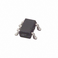
MAX4230AXK+T Maxim Integrated Products, MAX4230AXK+T Datasheet - Page 8

MAX4230AXK+T
Manufacturer Part Number
MAX4230AXK+T
Description
IC OP AMP R-R W/SD SC70-5
Manufacturer
Maxim Integrated Products
Datasheet
1.MAX4231EVKIT.pdf
(28 pages)
Specifications of MAX4230AXK+T
Amplifier Type
General Purpose
Number Of Circuits
1
Output Type
Rail-to-Rail
Slew Rate
10 V/µs
Gain Bandwidth Product
10MHz
Current - Input Bias
50pA
Voltage - Input Offset
850µV
Current - Supply
1.2mA
Current - Output / Channel
200mA
Voltage - Supply, Single/dual (±)
2.7 V ~ 5.5 V, ±1.35 V ~ 2.5 V
Operating Temperature
-40°C ~ 125°C
Mounting Type
Surface Mount
Package / Case
SC-70-5, SC-88A, SOT-323-5, SOT-353, 5-TSSOP
Number Of Channels
1
Voltage Gain Db
100 dB
Common Mode Rejection Ratio (min)
52 dB
Input Offset Voltage
6 mV
Operating Supply Voltage
3 V, 5 V
Maximum Power Dissipation
247 mW
Maximum Operating Temperature
+ 125 C
Mounting Style
SMD/SMT
Maximum Dual Supply Voltage
+/- 2.5 V
Minimum Operating Temperature
- 40 C
Lead Free Status / RoHS Status
Lead free / RoHS Compliant
-3db Bandwidth
-
Lead Free Status / Rohs Status
Details
Other names
MAX4230AXK+T
MAX4230AXK+TTR
MAX4230AXK+TTR
High-Output-Drive, 10MHz, 10V/µs,
Rail-to-Rail I/O Op Amps with Shutdown in SC70
The MAX4230–MAX4234 CMOS operational amplifiers
have parallel-connected n- and p-channel differential
input stages that combine to accept a common-mode
range extending to both supply rails. The n-channel
stage is active for common-mode input voltages typi-
cally greater than (V
stage is active for common-mode input voltages typi-
cally less than (V
Warning: Due to the high output current drive, this op
amp can exceed the absolute maximum power-dissi-
pation rating. As a general rule, as long as the peak cur-
rent is less than or equal to 40mA, the maximum package
power dissipation is not exceeded for any of the package
8
M AX42 30
SOT 23 /
SC7 0
_______________________________________________________________________________________
—
—
—
—
—
—
—
—
—
—
1
2
3
4
5
SC7 0/Th in
M AX42 31
SOT 23 /
µ DF N
—
—
—
—
—
—
—
—
—
1
2
3
4
6
5
Applications Information
DD
- 1.2V).
Package Power Dissipation
M A X42 31
SS
U CSP
Detailed Description
B1
A1
B2
A2
A3
B3
—
—
—
—
—
—
—
—
—
Rail-to-Rail Input Stage
+ 1.2V), and the p-channel
M AX42 32
SOT 23 /
µ M A X
PIN
—
—
—
—
—
—
—
4
8
3
2
1
5
6
7
M A X4 2 3 3
µ M A X
5, 6
10
—
—
—
—
—
—
4
3
2
1
7
8
9
M AX42 33
C4, A4
U CSP
C3
C2
C1
B4
B1
A3
A2
A1
—
—
—
—
—
—
M AX42 34
T SSOP/
types offered. There are some exceptions to this rule,
however. The absolute maximum power-dissipation rating
of each package should always be verified using the fol-
lowing equations. The equation below gives an approxi-
mation of the package power dissipation:
where:
V
current and RMS voltage from V
ing current.
I
and the load.
θ = phase difference between the voltage and the cur-
rent. For resistive loads, COS θ = 1.
10, 12
RMS
9, 13
8, 14
RMS
SO
11
—
—
—
—
4
3
2
1
5
6
7
= RMS current flowing out of or into the op amp
= RMS voltage from V
IN 3- , IN 4- Inverting Input to Amplifiers 3 and 4
SHDN1,
SHDN2
NAME
SHDN,
OUT3,
OUT1
OUT2
OUT4
IN3+,
IN1+
IN2+
OUT
IN1-
IN2-
V
IN+
V
IN-
DD
SS
P
IC DISS
(
Noninverting Input
Negative Supply Input. Connect to
ground for single-supply operation.
Inverting Input
Amplifier Output
Positive Supply Input
Shutdown Control. Tie to high for normal
operation.
Noninverting Input to Amplifier 1
Inverting Input to Amplifier 1
Amplifier 1 Output
Noninverting Input to Amplifier 2
Inverting Input to Amplifier 2
Amplifier 2 Output
Noninverting Input to Amplifiers 3 and 4
Amplifiers 3 and 4 Outputs
)
≅
V
RMS RMS
DD
Pin Description
I
FUNCTION
to V
OUT
OUT
COS
to V
when sourcing
θ
SS
when sink-


