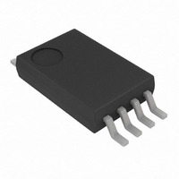
MCP601-I/ST Microchip Technology, MCP601-I/ST Datasheet - Page 15

MCP601-I/ST
Manufacturer Part Number
MCP601-I/ST
Description
IC OPAMP SNGL SUPPLY R-R 8TSSOP
Manufacturer
Microchip Technology
Datasheet
1.MCP601T-IOT.pdf
(34 pages)
Specifications of MCP601-I/ST
Amplifier Type
General Purpose
Number Of Circuits
1
Output Type
Rail-to-Rail
Slew Rate
2.3 V/µs
Gain Bandwidth Product
2.8MHz
Current - Input Bias
1pA
Voltage - Input Offset
700µV
Current - Supply
230µA
Current - Output / Channel
22mA
Voltage - Supply, Single/dual (±)
2.7 V ~ 6 V
Operating Temperature
-40°C ~ 85°C
Mounting Type
Surface Mount
Package / Case
8-TSSOP
Lead Free Status / RoHS Status
Lead free / RoHS Compliant
-3db Bandwidth
-
Available stocks
Company
Part Number
Manufacturer
Quantity
Price
Company:
Part Number:
MCP601-I/ST
Manufacturer:
MICROCHIP
Quantity:
12 000
4.8.2
Instrumentation amplifiers have a differential input that
subtracts one input voltage from another and rejects
common mode signals. These amplifiers also provide a
single-ended output voltage.
The three-op amp instrumentation amplifier is illustrated
in
gain operation, while one disadvantage is that the
common mode input range is reduced as R
larger.
FIGURE 4-10:
Instrumentation Amplifier.
The two-op amp instrumentation amplifier is shown in
Figure
the three-op amp version, its main drawbacks are that
the common mode range is reduced with higher gains
and it must be configured in gains of two or higher.
FIGURE 4-11:
Instrumentation Amplifier.
Both instrumentation amplifiers should use a bulk
bypass capacitor of at least 1 µF. The CMRR of these
amplifiers will be set by both the op amp CMRR and
resistor matching.
© 2007 Microchip Technology Inc.
Figure
V
V
V
V
V
1
2
REF
2
1
4-11. While its power consumption is lower than
V
V
R
R
OUT
OUT
+
MCP60X
–
–
MCP60X
+
4-10. One advantage of this approach is unity-
G
1
INSTRUMENTATION AMPLIFIER
CIRCUITS
R
R
=
=
2
2
+
MCP60X
-
(
(
V
V
1
1
R
–
–
2
V
V
Three-Op Amp
R
Two-Op Amp
2
2
R
R
) 1
) 1
G
3
3
⎛
⎝
⎛
⎝
+
+
R
2R
-------- -
R
----- -
R
R
–
MCP60X
+
2
1
2
G
2
+
⎞ R
⎠
R
R
2R
-------- -
⎛
⎝
R
----- -
R
4
4
G
MCP60X
-
+
4
3
1
⎞
⎠
⎞
⎠
+
+
V
R
REF
V
V
1
REF
REF
2
V
/R
V
OUT
G
OUT
gets
4.8.3
The MCP601/1R/2/3/4 op amps can be used to easily
convert the signal from a sensor that produces an
output current (such as a photo diode) into a voltage (a
transimpedance amplifier). This is implemented with a
single resistor (R
amplifiers shown in
optional capacitor (C
these circuits.
A photodiode configured in the Photovoltaic mode has
zero voltage potential placed across it
this mode, the light sensitivity and linearity is
maximized, making it best suited for precision
applications. The key amplifier specifications for this
application are: low input bias current, low noise,
common mode input voltage range (including ground),
and rail-to-rail output.
FIGURE 4-12:
In contrast, a photodiode that is configured in the
Photoconductive mode has a reverse bias voltage
across the photo-sensing element
decreases the diode capacitance, which facilitates
high-speed
communications). The design trade-off is increased
diode leakage current and linearity errors. The op amp
needs to have a wide Gain Bandwidth Product
(GBWP).
FIGURE 4-13:
Detector.
Light
Light
MCP601/1R/2/3/4
I
I
D1
PHOTO DETECTION
D1
V
operation
BIAS
D
D
2
) in the feedback loop of the
1
1
Figure 4-12
2
) sometimes provides stability for
Photovoltaic Mode Detector.
Photoconductive Mode
–
MCP60X
+
MCP60X
+
–
C
R
C
R
(e.g.,
2
2
2
2
V
V
and
DD
DD
high-speed
(Figure
DS21314G-page 15
Figure
V
V
(Figure
V
OUT
BIAS
OUT
V
V
4-13). This
= I
OUT
< 0V
4-13. The
= I
OUT
4-12). In
D1
D1
digital
R
R
2
2


