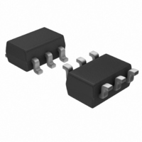
LT1782HS6#TR Linear Technology, LT1782HS6#TR Datasheet - Page 12

LT1782HS6#TR
Manufacturer Part Number
LT1782HS6#TR
Description
IC OPAMP R-R IN/OUT SOT23-6
Manufacturer
Linear Technology
Series
Over-The-Top®r
Datasheet
1.LT1782IS5TRMPBF.pdf
(16 pages)
Specifications of LT1782HS6#TR
Amplifier Type
General Purpose
Number Of Circuits
1
Output Type
Rail-to-Rail
Slew Rate
0.075 V/µs
Gain Bandwidth Product
225kHz
Current - Input Bias
8nA
Voltage - Input Offset
500µV
Current - Supply
45µA
Current - Output / Channel
30mA
Voltage - Supply, Single/dual (±)
2.5 V ~ 18 V, ±1.25 V ~ 9 V
Operating Temperature
-40°C ~ 125°C
Mounting Type
Surface Mount
Package / Case
SOT-23-6
Lead Free Status / RoHS Status
Contains lead / RoHS non-compliant
-3db Bandwidth
-
Other names
LT1782HS6TR
Available stocks
Company
Part Number
Manufacturer
Quantity
Price
APPLICATIONS INFORMATION
LT1782
sourcing current is reduced to 10mA at 3V total supplies
as noted in the Electrical Characteristics section.
The LT1782 is internally compensated to drive at least
600pF of capacitance under any output loading condi-
tions. A 0.22µF capacitor in series with a 150Ω resistor
between the output and ground will compensate these
amplifiers for larger capacitive loads, up to 10,000pF, at
all output currents.
Distortion
There are two main contributors to distortion in op amps:
output crossover distortion as the output transitions from
sourcing to sinking current, and distortion caused by non-
linear common mode rejection. If the op amp is operating
inverting, there is no common mode induced distortion.
If the op amp is operating in the PNP input stage (input is
not within 0.8V of V
100dB. When the LT1782 switches between input stages,
there is significant nonlinearity in the CMRR. Lower load
resistance increases the output crossover distortion but
has no effect on the input stage transition distortion. For
lowest distortion, the LT1782 should be operated single
supply, with the output always sourcing current and with
SIMPLIFIED SCHEMATIC
12
SHDN
Q26
J1
Q25
Q23
+
2µA
+
Q24
), the CMRR is very good, typically
R1
30k
Q5
Q1
Q4
–IN
+IN
Q6
R2
R3
6k
6k
D4
D5
Q9
Q7
Q8
D1
Q10
the input voltage swing between ground and (V
See the Typical Performance Characteristics curves,
“Total Harmonic Distortion + Noise vs Ouput Voltage
Amplitude.”
Gain
The open-loop gain is almost independent of load when
the output is sourcing current. This optimizes performance
in single supply applications where the load is returned to
ground. The typical performance curve of open-loop gain
for various loads shows the details.
Shutdown
The 6-lead part includes a shutdown feature that disables
the part, reducing quiescent current and making the output
high impedance. The part can be shut down by bringing
the SHDN pin 1.2V or more above V
the supply current is about 5µA and the output leakage
current is less than 1µA (V
tion, the SHDN pin can be tied to V
the Typical Performance Characteristics curves, “Supply
Current vs Shutdown Pin Voltage.”
Q11
Q2
Q12
Q13
R4
40k
Q14
R5
40k
–
Q15
≤ V
D3
OUT
Q16
Q3
≤ V
–
–
+
or left floating. See
. When shut down,
). In normal opera-
Q17
Q18
Q19
Q20
+
– 0.8V).
Q22
Q21
1782 SS
1782fc
V
OUT
V
+
–


