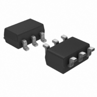
LT6200IS6-5#TR Linear Technology, LT6200IS6-5#TR Datasheet - Page 9

LT6200IS6-5#TR
Manufacturer Part Number
LT6200IS6-5#TR
Description
IC OP AMP 800MHZ R-R I/O SOT23-6
Manufacturer
Linear Technology
Datasheet
1.LT6200CS6TRMPBF.pdf
(26 pages)
Specifications of LT6200IS6-5#TR
Amplifier Type
Buffer
Number Of Circuits
1
Output Type
Rail-to-Rail
Slew Rate
250 V/µs
Gain Bandwidth Product
800MHz
Current - Input Bias
23µA
Voltage - Input Offset
2500µV
Current - Supply
20mA
Current - Output / Channel
90mA
Voltage - Supply, Single/dual (±)
2.5 V ~ 12.6 V, ±1.25 V ~ 6.3 V
Operating Temperature
-40°C ~ 85°C
Mounting Type
Surface Mount
Package / Case
SOT-23-6
Lead Free Status / RoHS Status
Contains lead / RoHS non-compliant
-3db Bandwidth
-
Available stocks
Company
Part Number
Manufacturer
Quantity
Price
ELECTRICAL CHARACTERISTICS
temperature range. Excludes the LT6201 in the DD package (Note 3). V
otherwise noted. (Note 5)
SYMBOL
V
V
I
ΔI
I
A
CMRR
PSRR
V
V
I
I
I
V
V
t
t
SR
FPBW
Note 1: Stresses beyond those listed under Absolute Maximum Ratings
may cause permanent damage to the device. Exposure to any Absolute
Maximum Rating condition for extended periods may affect device
reliability and lifetime
B
OS
SC
S
SHDN
ON
OFF
OS
OS
OL
OH
L
H
VOL
B
TC
PARAMETER
Input Offset Voltage
Input Offset Voltage Match
(Channel-to-Channel) (Note 11)
Input Offset Voltage Drift (Note 8)
Input Bias Current
I
I
Input Offset Current
Large-Signal Gain
Common Mode Rejection Ratio
CMRR Match (Channel-to-Channel) (Note 11)
Power Supply Rejection Ratio
PSRR Match (Channel-to-Channel) (Note 6)
Output Voltage Swing LOW (Note 7)
Output Voltage Swing HIGH (Note 7)
Short-Circuit Current
Supply Current
Disabled Supply Current
SHDN Pin Current
V
V
Shutdown Output Leakage Current
Turn-On Time
Turn-Off Time
Slew Rate
Full Power Bandwidth (Note 9)
B
B
SHDN
SHDN
Shift
Match (Channel-to-Channel) (Note 11)
Pin Input Voltage LOW
Pin Input Voltage HIGH
CONDITIONS
V
V
V
V
V
V
V
V
V
V
V
V
V
V
V
V
V
V
V
V
No Load
I
I
No Load
I
I
V
V
V
V
V
A
A
LT6200-5
LT6200-10
V
SINK
SINK
SOURCE
SINK
CM
CM
CM
CM
CM
CM
CM
CM
CM
CM
CM
CM
CM
O
O
CM
CM
CM
S
S
SHDN
SHDN
SHDN
SHDN
SHDN
OUT
V
V
= ±1.5V to ±5V
= ±4.5V, R
= ±2V, R
= ±1.5V to ±5V
= –1, R
= –10, R
= Half Supply
= V
= V
= 0V
= V
= Half Supply
= Half Supply
= V
= V
= V
= Half Supply
= V
= V
= V
= –2V to 2V
= –2V to 2V
The
= 5mA
= 20mA
= 20mA
= 3V
= 0.3V
= 0.3V
= 0.3V
= 0.3V to 4.5V, R
= 4.5V to 0.3V, R
+
+
–
–
+
–
–
–
–
= 5mA
to V
●
to V
to V
P-P
L
L
L
= 1k, V
denotes the specifi cations which apply over –40°C < T
= 100
(LT6200-10)
+
L
= 1k, V
+
+
= 1k
Note 2: Inputs are protected by back-to-back diodes. If the differential
input voltage exceeds 0.7V, the input current must be limited to less
than 40mA. This parameter is guaranteed to meet specifi ed performance
through design and/or characterization. It is not 100% tested.
O
S
O
= 4V
= ±5V, V
= 4V
L
L
= 100Ω, V
= 100Ω, V
CM
= V
S
S
= 5V
= 5V
OUT
= 0V, V
LT6200-10/LT6201
LT6200/LT6200-5
l
l
l
l
l
l
l
l
l
l
l
l
l
l
l
l
l
l
l
l
l
l
l
l
l
l
l
l
l
l
l
l
l
l
l
l
l
l
l
l
SHDN
V
+
MIN
–40
–50
±60
125
260
7.5
46
65
75
75
60
60
31
27
– 0.5
= OPEN, unless
13.5
TYP
–10
–23
100
105
100
170
125
265
±90
215
130
180
180
370
1.9
3.5
3.5
0.2
0.4
8.2
1.3
3.5
1.6
0.1
31
80
90
65
16
60
85
25
44
39
8
4
1
A
MAX
< 85°C
125
310
150
230
480
295
4.5
7.5
7.5
3.6
2.1
0.3
24
18
68
12
10
10
15
75
29
75
2
UNITS
62001fd
μV/ºC
V/mV
V/mV
9
V/μs
V/μs
V/μs
MHz
mV
mV
mV
mV
mV
mV
mV
mV
mV
mV
mV
mA
mA
mA
μA
μA
μA
μA
μA
μA
μA
μA
dB
dB
dB
dB
dB
μA
μA
ns
ns
V
V


