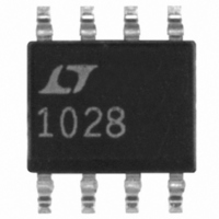
LT1028CS8 Linear Technology, LT1028CS8 Datasheet

LT1028CS8
Specifications of LT1028CS8
Available stocks
Related parts for LT1028CS8
LT1028CS8 Summary of contents
Page 1
... The LT1028/LT1128’s voltage noise is less than the noise impedance transducer or audio amplifier applications, the LT1028/LT1128’s contribution to total system noise will be negligible. , LTC and LT are registered trademarks of Linear Technology Corporation DEMODULATOR SYNC + OUTPUT TO LT1028 DEMODULATOR – ...
Page 2
... NC 7 LT1028MJ8 NC 8 LT1028ACJ8 LT1028CJ8 SW PACKAGE 16-LEAD PLASTIC SOL LT1128AMJ8 T = 140 C, JMAX LT1128MJ8 NOTE: THIS DEVICE IS NOT RECOM- MENDED FOR NEW DESIGNS LT1128CJ8 ORDER PART NUMBER TOP VIEW LT1028CS8 TRIM LT1128CS8 – OUT S8 PART MARKING OVER- 5 COMP 1028 1128 = 140 C/W JA ...
Page 3
ELECTRICAL C HARA TERISTICS C SYMBOL PARAMETER V Input Offset Voltage OS V Long Term Input Offset OS Time Voltage Stability I Input Offset Current OS I Input Bias Current B e Input Noise Voltage n Input Noise Voltage Density ...
Page 4
LT1028/LT1128 ELECTRICAL C HARA TERISTICS 15V, unless otherwise noted SYMBOL PARAMETER V Input Offset Voltage OS V Average Input Offset Drift OS Temp I Input Offset Current OS I Input ...
Page 5
W U TYPICAL PERFOR A 10Hz Voltage Noise Distribution 180 V = 15V S 158 160 148 A 500 UNITS 140 MEASURED FROM 4 RUNS 120 100 ...
Page 6
LT1028/LT1128 W U TYPICAL PERFOR A Distribution of Input Offset Voltage 15V 800 UNITS TESTED 16 FROM FOUR RUNS –50 –40 –30 ...
Page 7
W U TYPICAL PERFOR A Voltage Gain vs Frequency 160 V = 15V S 140 120 100 LT1128 LT1028 –20 0.01 0 100 1k ...
Page 8
LT1028/LT1128 W U TYPICAL PERFOR A LT1028 Large-Signal Transient Response 10V –10V 1 s/DIV A = – 2k 15pF LT1128 Large-Signal Transient Response 10V 0V –10V 2 s/DIV A = ...
Page 9
W U TYPICAL PERFOR A Common Mode Limit Over Temperature + V – –2 S – 15V S – 15V – V –50 – ...
Page 10
... In summary, the LT1028/LT1128 are the optimum ampli- fiers for noise performance, provided that the source resistance is kept low. The following table depicts which op amp manufactured by Linear Technology should be used to minimize noise, as the source resistance is in- creased beyond the LT1028/LT1128’s level of usefulness. ...
Page 11
PPLICATI FOR ATIO Noise Testing – Voltage Noise The LT1028/LT1128’s RMS voltage noise density can be accurately measured using the Quan Tech Noise Analyzer, Model 5173 or an equivalent noise tester. Care should be ...
Page 12
LT1028/LT1128 PPLICATI S I FOR ATIO Noise Testing – Current Noise Current noise density ( defined by the following n formula, and can be measured in the circuit shown – (31 18.4nV/ ...
Page 13
PPLICATI S I FOR ATIO terminals, can exceed the inherent drift of the amplifier unless proper care is exercised. Air currents should be minimized, package leads should be short, the two input leads should be close ...
Page 14
LT1028/LT1128 PPLICATI S I FOR ATIO only used to cut noise bandwidth, a similar effect F can be achieved using the over-compensation terminal. The Gain, Phase plot also shows that phase margin is ...
Page 15
U TYPICAL APPLICATIO S Paralleling Amplifiers to Reduce Voltage Noise + 1.5k A1 LT1028 – 7.5 470 + 1.5k A2 LT1028 – 7.5 470 + 1.5k An LT1028 – 7.5 470 1. ASSUME VOLTAGE NOISE OF LT1028 AND 7.5 SOURCE ...
Page 16
LT1028/LT1128 U TYPICAL APPLICATIO S C1 0.047 2k R2 560 INPUT 1028/1128 TA11 16 Super Low Distortion Variable Sine Wave Oscillator R1 C2 0.047 LT1028 – 5.6k 2.4k 10pF 22k 15 F 10k – 2N4338 100k ...
Page 17
CHE AGRA I NULL 130 130 NULL 900 A 900 NON- Q7 INVERTING INPUT 4 4.5 A 4.5 A ...
Page 18
LT1028/LT1128 PACKAGE DESCRIPTIO OBSOLETE PACKAGE 0.045 – 0.068 (1.143 – 1.727) FULL LEAD OPTION 0.300 BSC (0.762 BSC) 0.008 – 0.018 (0.203 – 0.457) NOTE: LEAD DIMENSIONS APPLY TO SOLDER DIP/PLATE OR TIN PLATE LEADS 0.300 – 0.325 (7.620 – ...
Page 19
... FOR SOLDER DIP LEAD FINISH, LEAD DIAMETER IS (0.406 – 0.610) Information furnished by Linear Technology Corporation is believed to be accurate and reliable. However, no responsibility is assumed for its use. Linear Technology Corporation makes no represen- tation that the interconnection of its circuits as described herein will not infringe on existing patent rights Package 16-Lead Plastic Small Outline (Narrow ...
Page 20
... LTC1043 6 13 LT1028 – 4 10k – COMMENTS Slew Rate = 140V/ s, Low Distortion at 5MHz: –80dBc www.linear.com 10k LM301A + 8 3 – LT1012 – 1 –5V 30pF 4 –5V 1028/1128 TA12 1028fa LT/CP 0901 1.5K REV A • PRINTED IN USA LINEAR TECHNOLOGY CORPORATION 1992 DC OUT ...


