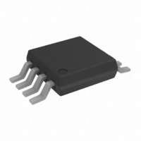
AD8626ARMZ Analog Devices Inc, AD8626ARMZ Datasheet - Page 15

AD8626ARMZ
Manufacturer Part Number
AD8626ARMZ
Description
IC OPAMP JFET 5MHZ DUAL LP 8MSOP
Manufacturer
Analog Devices Inc
Type
General Purpose Amplifierr
Datasheet
1.AD8627AKSZ-REEL7.pdf
(20 pages)
Specifications of AD8626ARMZ
Slew Rate
5 V/µs
Amplifier Type
J-FET
Number Of Circuits
2
Output Type
Rail-to-Rail
Gain Bandwidth Product
5MHz
Current - Input Bias
0.25pA
Voltage - Input Offset
350µV
Current - Supply
710µA
Current - Output / Channel
15mA
Voltage - Supply, Single/dual (±)
5 V ~ 26 V, ±2.5 V ~ 13 V
Operating Temperature
-40°C ~ 85°C
Mounting Type
Surface Mount
Package / Case
8-MSOP, Micro8™, 8-uMAX, 8-uSOP,
Op Amp Type
Precision
No. Of Amplifiers
2
Bandwidth
5MHz
Supply Voltage Range
5V To 26V
Amplifier Case Style
MSOP
No. Of Pins
8
Operating Temperature Range
-40°C To +85°C
Rail/rail I/o Type
Rail to Rail Output
Number Of Elements
2
Unity Gain Bandwidth Product
5MHz
Common Mode Rejection Ratio
66dB
Input Offset Voltage
500uV
Input Bias Current
1pA
Single Supply Voltage (typ)
9/12/15/18/24V
Dual Supply Voltage (typ)
±3/±5/±9/±12V
Voltage Gain In Db
107.23dB
Power Supply Rejection Ratio
80dB
Power Supply Requirement
Single/Dual
Shut Down Feature
No
Single Supply Voltage (min)
5V
Single Supply Voltage (max)
26V
Dual Supply Voltage (min)
±2.5V
Dual Supply Voltage (max)
±13V
Technology
BiFET
Operating Temp Range
-40C to 85C
Operating Temperature Classification
Industrial
Mounting
Surface Mount
Pin Count
8
Package Type
MSOP
Lead Free Status / RoHS Status
Lead free / RoHS Compliant
-3db Bandwidth
-
Lead Free Status / Rohs Status
Compliant
Available stocks
Company
Part Number
Manufacturer
Quantity
Price
Company:
Part Number:
AD8626ARMZ
Manufacturer:
AMD
Quantity:
6 255
Part Number:
AD8626ARMZ
Manufacturer:
ADI/亚德诺
Quantity:
20 000
Company:
Part Number:
AD8626ARMZ-REEL
Manufacturer:
ADI
Quantity:
75
MINIMIZING INPUT CURRENT
The AD862x is guaranteed to 1 pA maximum input current
with a ±13 V supply voltage at room temperature. Careful
attention to how the amplifier is used maintains or possibly
betters this performance. The amplifier’s operating temperature
should be kept as low as possible. Like other JFET input ampli-
fiers, the AD862x’s input current doubles for every 10°C rise in
junction temperature, as illustrated in Figure 8. On-chip power
dissipation raises the device operating temperature, causing an
increase in input current. Reducing supply voltage to cut power
dissipation reduces the AD862x’s input current. Heavy output
loads can also increase chip temperature; maintaining a
minimum load resistance of 1 kΩ is recommended.
The AD862x is designed for mounting on PC boards. Main-
taining picoampere resolution in those environments requires
a lot of care. Both the board and the amplifier’s package have
finite resistance. Voltage differences between the input pins and
other pins, as well as PC board metal traces may cause parasitic
currents larger than the AD862x’s input current, unless special
precautions are taken. To ensure the best result, refer to the ADI
website for proper board layout seminar materials. Two
common methods of minimizing parasitic leakages that should
be used are guarding of the input lines and maintaining
adequate insulation resistance.
Contaminants, such as solder flux on the board’s surface and
the amplifier’s package, can greatly reduce the insulation
resistance between the input pin and traces with supply or
signal voltages. Both the package and the board must be kept
clean and dry.
Rev. E | Page 15 of 20
PHOTODIODE PREAMPLIFIER APPLICATION
The low input current and offset voltage levels of the AD862x,
together with its low voltage noise, make this amplifier an
excellent choice for preamplifiers used in sensitive photodiode
applications. In a typical photovoltaic preamp circuit, shown in
Figure 45, the output of the amplifier is equal to
where:
ID = photodiode signal current (A).
R
R
P = light power incident to photodiode surface, in W.
The amplifier’s input current, I
error proportional to the value of the feedback resistor. The
offset voltage error, V
photodiode’s finite shunt resistance, R
The resulting output voltage error, V
A shunt resistance on the order of 100 MΩ is typical for a small
photodiode. Resistance R
drops by a factor of two for every 10°C rise in temperature. In
the AD862x, both the offset voltage and drift are low, which
helps minimize these errors. With I
50 mV, V
Figure 45 results in an SNR value of 95 dB for a signal bandwidth
of 30 kHz.
p
f
= value of the feedback resistor, in Ω.
= photodiode sensitivity (A/W).
V
V
OUT
E
= 1
E
⎛
⎜
⎜
⎝
for Figure 45 is very negligible. Also, the circuit in
R
100M Ω
=
Figure 45. A Photodiode Model Showing DC Error
D
−
+
PHOTODIODE
ID(R
R
R
D
f
⎞
⎟
⎟
⎠
V
f
I
B
)
OS
OS
=
, causes a small current error due to the
+
−
AD8625/AD8626/AD8627
C4
15pF
D
R
R
is a junction resistance that typically
p
f
(P)R
(I
I
B
B
B
, contributes an output voltage
)
f
V
B
OS
E
values of 1 pA and V
, is equal to
D
.
1.5M
5pF
C
R
F
F
AD8627
Ω
OUTPUT
OS
of


