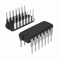
HA1-5320-5 Intersil, HA1-5320-5 Datasheet - Page 5

HA1-5320-5
Manufacturer Part Number
HA1-5320-5
Description
IC AMPLIFIER SAMPLE-HOLD 14-CDIP
Manufacturer
Intersil
Datasheet
1.HA9P5320-5Z.pdf
(8 pages)
Specifications of HA1-5320-5
Amplifier Type
Sample and Hold
Number Of Circuits
1
Slew Rate
45 V/µs
Gain Bandwidth Product
2MHz
Current - Input Bias
100nA
Voltage - Input Offset
500µV
Current - Supply
11mA
Current - Output / Channel
10mA
Voltage - Supply, Single/dual (±)
±13.5 V ~ 20 V
Operating Temperature
0°C ~ 75°C
Mounting Type
Through Hole
Package / Case
14-CDIP (0.300", 7.62mm)
Lead Free Status / RoHS Status
Contains lead / RoHS non-compliant
Output Type
-
-3db Bandwidth
-
Available stocks
Company
Part Number
Manufacturer
Quantity
Price
Company:
Part Number:
HA1-5320-5
Manufacturer:
HAR/INT
Quantity:
720
Company:
Part Number:
HA1-5320-5
Manufacturer:
HAR/INT
Quantity:
720
Company:
Part Number:
HA1-5320-5
Manufacturer:
HARRIS
Quantity:
17
Test Circuits and Waveforms
NOTES:
Application Information
The HA-5320 has the uncommitted differential inputs of an
op amp, allowing the Sample and Hold function to be
Intersil Application Note AN517 for a collection of circuit
ideas.
Layout
A printed circuit board with ground plane is recommended
for best performance. Bypass capacitors (0.01µF to 0.1µF,
ceramic) should be provided from each power supply
terminal to the Supply Ground terminal on pin 13.
The ideal ground connections are pin 6 (SIG. Ground)
directly to the system Signal Ground, and pin 13 (Supply
Ground) directly to the system Supply Common.
13. Observe the “hold step” voltage V
14. Compute charge transfer: Q = V
combined with many conventional op amp circuits. See the
S/H CONTROL
S/H CONTROL
SINE WAVE
100kHz
10V
INPUT
P-P
V
FIGURE 2. CHARGE TRANSFER TEST
O
V IN
ANALOG
MUX OR
SWITCH
A
IN
5
V
P
P
P
C
.
H
CONTROL
.
INPUT
FIGURE 4. HOLD MODE FEEDTHROUGH ATTENUATION
S/H
FIGURE 1. CHARGE TRANSFER AND DRIFT CURRENT
14
1
2
S/H CONTROL
-IN
+IN
COMMON
SUPPLY
SUPPLY
13
HOLD (+3.5V)
SAMPLE (0V)
GND
TO
14
1
2
-INPUT
+INPUT
S/H CONTROL
9
V+
11
C
NC
HA-5320
EXT
HA-5320
SIGNAL
COM
GND
REF
6
TO
HA-5320
5
V-
NOTES:
15. Observe the voltage “droop”, ∆V
16. Measure the slope of the output during hold, ∆V
Hold Capacitor
The HA-5320 includes a 100pF MOS hold capacitor,
sufficient for most high speed applications (the Electrical
Specifications section is based on this internal capacitor).
Additional capacitance may be added between pins 7 and
11. This external hold capacitance will reduce droop rate at
the expense of acquisition time, and provide other trade-offs
as shown in the Performance Curves.
If an external hold capacitor C
bandwidth capacitor of value 0.1C
from pin 8 to ground. Exact value and type are not critical.
The hold capacitor C
resistance and low dielectric absorption, to minimize droop
errors. Polystyrene dielectric is a good choice for operating
temperatures up to 85°C. Teflon® and glass dielectrics offer
good performance to 125°C and above.
COMP.
S/H CONTROL
8
INT.
NC
OUT
compute drift current: I
OUTPUT
7
V
O
(C
FIGURE 3. DRIFT CURRENT TEST
H
V
7
8
11
OUT
= 100pF)
NC
NC
EXT
D
should have high insulation
NOTE:
Feedthrough in
V
dB
= C
OUT
V
H
=
O
EXT
∆V
= V
20
O
/∆t.
O
log
EXT
∆t
P-P
is used, then a noise
/∆t.
V
-------------- -
, Hold Mode, V
V
OUT
should be connected
IN
where:
O
∆V
/∆t, and
HOLD (+3.5V)
SAMPLE (0V)
August 24, 2005
O
IN
= V
FN2857.7
P-P
.


