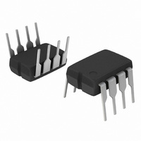
MC33072PG ON Semiconductor, MC33072PG Datasheet - Page 12

MC33072PG
Manufacturer Part Number
MC33072PG
Description
IC OPAMP DUAL 4.5MHZ 8DIP
Manufacturer
ON Semiconductor
Specifications of MC33072PG
Amplifier Type
General Purpose
Number Of Circuits
2
Slew Rate
13 V/µs
Gain Bandwidth Product
4.5MHz
Current - Input Bias
100nA
Voltage - Input Offset
1000µV
Current - Supply
1.9mA
Current - Output / Channel
30mA
Voltage - Supply, Single/dual (±)
3 V ~ 44 V, ±1.5 V ~ 22 V
Operating Temperature
-40°C ~ 85°C
Mounting Type
Through Hole
Package / Case
8-DIP (0.300", 7.62mm)
Number Of Channels
2
Common Mode Rejection Ratio (min)
70 dB
Input Voltage Range (max)
Positive Rail - 1.8 V
Input Voltage Range (min)
Negative Rail
Input Offset Voltage
5 mV
Input Bias Current (max)
500 nA
Operating Supply Voltage
44 V
Supply Current
3.8 mA
Maximum Operating Temperature
+ 85 C
Minimum Operating Temperature
- 40 C
Dual Supply Voltage
+/- 3 V, +/- 5 V, +/- 9 V
Maximum Dual Supply Voltage
+/- 22 V
Minimum Dual Supply Voltage
+/- 1.5 V
Mounting Style
Through Hole
Shutdown
No
Supply Voltage (max)
44 V
Supply Voltage (min)
3 V
Technology
Bipolar
Voltage Gain Db
100 dB
Bandwidth
4.5 MHz
Channel Separation
120
Common Mode Rejection Ratio
97
Current, Input Bias
700 nA
Current, Input Offset
300 nA
Current, Output
30 mA
Current, Supply
2.8 mA
Harmonic Distortion
0.02 %
Number Of Amplifiers
Dual
Package Type
PDIP-8
Resistance, Input
150 Megohms
Temperature, Operating, Range
-40 to +85 °C
Voltage, Gain
20 V/mV
Voltage, Input
±15 V
Voltage, Noise
32 nV/sqrt Hz
Voltage, Offset
7 mV
Voltage, Output, High
13.4 V
Voltage, Output, Low
-13.5 V
Voltage, Supply
3 to 44 V
Lead Free Status / RoHS Status
Lead free / RoHS Compliant
Output Type
-
-3db Bandwidth
-
Lead Free Status / Rohs Status
Lead free / RoHS Compliant
Other names
MC33072PGOS
Available stocks
Company
Part Number
Manufacturer
Quantity
Price
Company:
Part Number:
MC33072PG
Manufacturer:
ON
Quantity:
12 100
V
V
O
in
2.63 V
V
V
V
Figure 38. AC Coupled Noninverting Amplifier
5.1 M
20 k
in
in
CC
≥ 0.2 Vdc
Figure 40. DC Coupled Inverting Amplifier
Figure 42. Active High−Q Notch Filter
36.6 mV
C
2.0 C
0.02
in
16 k
pp
R
32 k
0.01
Maximum Output Swing
4.75 V
C
1.0 M
1.0 k
pp
2.0 R
16 k
2.0 C
5.1 k
0.02
V
R
in
BW (-3.0 dB) = 45 kHz
100 k
+
MC34071
-
100 k
V
O
0
A
BW (-3.0 dB) = 450 kHz
V
MC34071
91 k
-
+
= 101
(Typical Single Supply Applications V
+
MC34071
-
A
V
1.0 M
f
f
C
o
o
= 10
O
= 1.0 kHz
=
4pRC
1
3.7 V
10 k
R
V
V
L
5.1 k
R
O
O
L
pp
http://onsemi.com
V
V
CC
O
12
V
Given f
A
Choose Value f
in
O
Then:
For less than 10% error from operational amplifier
where f
GBW = 4.5 MHz Typ.
= Gain at Center Frequency
0
o
= Center Frequency
2.5 V
1.1 k
V
R1
R3 =
o
in
and GBW are expressed in Hz.
5.6 k
R2
Figure 41. Unity Gain Buffer TTL Driver
Figure 39. AC Coupled Inverting Amplifier
o
, Q, A
pf
Figure 43. Active Bandpass Filter
Q
o
CC
C
68 k
MC34071
+
-
o
, C
0.047
= 5.0 V)
R1 =
A
C
0.047
V
C
V
= 10 BW (-3.0 dB) = 450 kHz
in
C
2H
370 mV
in
R3
o
0 to 10,000 pF
100 k
0.4 V
R2 =
10 k
2.2 k
V
pp
R3
CC
Cable
CC
4Q
MC34071
-
+
R1 R3
2
R1-R3
MC34071
0
+
-
100 k
V
CC
GBW
Q
o
f
o
f
H
H
o
o
o
< 0.1
MC54/74XX
= 30 kHz
= 10
= 1.0
C
O
TTL Gate
V
3.7 V
10 k
R
O
L
V
O
pp


