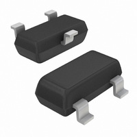
MAX810MTRG ON Semiconductor, MAX810MTRG Datasheet - Page 12

MAX810MTRG
Manufacturer Part Number
MAX810MTRG
Description
IC MPU SUPERVISORY 4.38V SOT23
Manufacturer
ON Semiconductor
Type
Simple Reset/Power-On Resetr
Datasheet
1.MAX810MTRG.pdf
(13 pages)
Specifications of MAX810MTRG
Number Of Voltages Monitored
1
Output
Push-Pull, Totem Pole
Reset
Active High
Reset Timeout
140 ms Minimum
Voltage - Threshold
4.38V
Operating Temperature
-40°C ~ 105°C
Mounting Type
Surface Mount
Package / Case
SOT-23-3, TO-236-3, Micro3™, SSD3, SST3
Monitored Voltage
1.2 V to 4.9 V
Undervoltage Threshold
4.38 V
Overvoltage Threshold
4.45 V
Manual Reset
No
Watchdog
No
Battery Backup Switching
No
Power-up Reset Delay (typ)
460 ms
Supply Voltage (max)
5.5 V
Supply Voltage (min)
1 V
Supply Current (typ)
0.8 uA
Mounting Style
SMD/SMT
Maximum Operating Temperature
+ 105 C
Chip Enable Signals
No
Internal Hysteresis
No
Minimum Operating Temperature
- 40 C
Operating Temperature Range
- 40 C to + 105 C
Output Type
Push-Pull
Power Fail Detection
No
Number Of Elements
1
Monitored Voltage 1 (typ)
1.2 to 4.9V
Threshold Voltage 1 (max)
4.45V
Watchdog Timer
No
Reset Active Time
460ms
Package Type
SOT-23
Operating Supply Voltage (min)
1.2V
Operating Supply Voltage (max)
5.5V
Reset Threshold Voltage (max)
4.45V
Reset Threshold Voltage (min)
4.31V
Family Name
MAX810
Operating Temp Range
-40C to 105C
Operating Temperature Classification
Industrial
Mounting
Surface Mount
Pin Count
3
Supply Current
0.0025mA
Lead Free Status / RoHS Status
Lead free / RoHS Compliant
Other names
MAX810MTRGOSTR
Available stocks
Company
Part Number
Manufacturer
Quantity
Price
Part Number:
MAX810MTRG
Manufacturer:
MAXIM/美信
Quantity:
20 000
A
A1
E
1
3
D
e
2
b
H
E
*For additional information on our Pb−Free strategy and soldering
details, please download the ON Semiconductor Soldering and
Mounting Techniques Reference Manual, SOLDERRM/D.
SEE VIEW C
0.037
0.95
0.035
0.9
0.031
PACKAGE DIMENSIONS
SOLDERING FOOTPRINT*
0.8
VIEW C
L1
http://onsemi.com
SOT−23 (TO236)
L
CASE 318−08
ISSUE AN
q
0.25
12
c
SCALE 10:1
0.037
0.95
NOTES:
1. DIMENSIONING AND TOLERANCING PER ANSI
2. CONTROLLING DIMENSION: INCH.
3. MAXIMUM LEAD THICKNESS INCLUDES LEAD
4. 318−01 THRU −07 AND −09 OBSOLETE, NEW
0.079
inches
Y14.5M, 1982.
FINISH THICKNESS. MINIMUM LEAD
THICKNESS IS THE MINIMUM THICKNESS OF
BASE MATERIAL.
STANDARD 318−08.
2.0
DIM
mm
A1
H
L1
A
b
c
D
E
e
L
E
MIN
0.89
0.01
0.37
0.09
2.80
1.20
1.78
0.10
0.35
2.10
MILLIMETERS
NOM
1.00
0.06
0.44
0.13
2.90
1.30
1.90
0.20
0.54
2.40
MAX
1.11
0.10
0.50
0.18
3.04
1.40
2.04
0.30
0.69
2.64
0.035
0.001
0.015
0.003
0.047
0.070
0.004
0.014
0.083
0.110
MIN
INCHES
0.040
0.002
0.018
0.005
0.051
0.075
0.008
0.021
0.094
NOM
0.114
0.044
0.004
0.020
0.007
0.120
0.055
0.081
0.012
0.029
0.104
MAX


