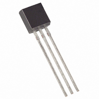
DS1813-10+T&R Maxim Integrated Products, DS1813-10+T&R Datasheet - Page 2

DS1813-10+T&R
Manufacturer Part Number
DS1813-10+T&R
Description
IC ECONORESET 5V W/PB 10% TO92-3
Manufacturer
Maxim Integrated Products
Series
EconoResetr
Type
Simple Reset/Power-On Resetr
Datasheet
1.DS1813R-5TR.pdf
(5 pages)
Specifications of DS1813-10+T&R
Number Of Voltages Monitored
1
Output
Open Drain or Open Collector
Reset
Active Low
Reset Timeout
100 ms Minimum
Voltage - Threshold
4.35V
Operating Temperature
-40°C ~ 85°C
Mounting Type
Through Hole
Package / Case
TO-92-3 (Standard Body), TO-226
Monitored Voltage
0 V to 5.5 V
Undervoltage Threshold
4.25 V
Overvoltage Threshold
4.49 V
Manual Reset
Resettable
Watchdog
No
Battery Backup Switching
No
Power-up Reset Delay (typ)
300 ms
Supply Voltage (max)
5.5 V
Supply Voltage (min)
0 V
Supply Current (typ)
40 uA
Mounting Style
Through Hole
Maximum Operating Temperature
+ 85 C
Chip Enable Signals
No
Minimum Operating Temperature
- 40 C
Output Type
Active Low or Open Drain
Power Fail Detection
Yes
Lead Free Status / RoHS Status
Lead free / RoHS Compliant
Other names
DS1813-10+TR
DS1813
OPERATION—POWER MONITOR
The DS1813 provides the functions of detecting out-of-tolerance power-supply conditions and warning a
processor-based system of impending power failure. When V
is detected as out-of-tolerance, the RST
CC
signal is asserted. On power-up, RST is kept active for approximately 150ms after the power supply has
reached the selected tolerance. This allows the power supply and microprocessor to stabilize before RST
is released.
OPERATION—PUSHBUTTON RESET
The DS1813 provides for a pushbutton switch for manual reset control. When the DS1813 is not in a reset
cycle, a pushbutton reset can be generated by pulling the RST pin low for at least 1µs. When the
pushbutton is held low, the RST is forced active low and will remain active low for about 150ms after the
pushbutton is released. See Figure 2 for an application example and Figure 3 for the timing diagram.
Figure 1. Block Diagram (Open-Drain Output)
Figure 2. Application Example
2 of 5


