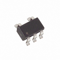
MAX6316LUK26CY+T Maxim Integrated Products, MAX6316LUK26CY+T Datasheet - Page 6

MAX6316LUK26CY+T
Manufacturer Part Number
MAX6316LUK26CY+T
Description
IC MPU/RESET CIRC 2.63V SOT23-5
Manufacturer
Maxim Integrated Products
Type
Simple Reset/Power-On Resetr
Datasheet
1.MAX6320PUK29CYT.pdf
(14 pages)
Specifications of MAX6316LUK26CY+T
Number Of Voltages Monitored
1
Output
Push-Pull, Totem Pole
Reset
Active Low
Reset Timeout
140 ms Minimum
Voltage - Threshold
2.63V
Operating Temperature
-40°C ~ 125°C
Mounting Type
Surface Mount
Package / Case
SOT-23-5, SC-74A, SOT-25
Monitored Voltage
1 V to 5.5 V
Undervoltage Threshold
2.591 V
Overvoltage Threshold
2.669 V
Output Type
Active Low, Push-Pull
Manual Reset
Resettable
Watchdog
Watchdog
Battery Backup Switching
No Backup
Power-up Reset Delay (typ)
200 ms
Supply Voltage (max)
5.5 V
Supply Voltage (min)
1 V
Supply Current (typ)
10 uA
Maximum Power Dissipation
571 mW
Maximum Operating Temperature
+ 125 C
Mounting Style
SMD/SMT
Minimum Operating Temperature
- 40 C
Power Fail Detection
No
Lead Free Status / RoHS Status
Lead free / RoHS Compliant
Other names
MAX6316LUK26CY+T
MAX6316LUK26CY+TTR
MAX6316LUK26CY+TTR
A microprocessor’s (µP) reset input starts or restarts the
µP in a known state. The reset output of the MAX6316–
MAX6322 µP supervisory circuits interfaces with the
reset input of the µP, preventing code-execution errors
during power-up, power-down, and brownout condi-
tions (see the Typical Operating Circuit ). The MAX6316/
MAX6317/MAX6318/MAX6320/MAX6321 are also capa-
ble of asserting a reset should the µP become stuck in
an infinite loop.
The MAX6316L/MAX6318LH/MAX6319LH feature an
active-low reset output, while the MAX6317H/
MAX6318_H/MAX6319_H/MAX6321HP/MAX6322HP
feature an active-high reset output. RESET is guaran-
teed to be a logic low and RESET is guaranteed to be a
logic high for V
The MAX6316–MAX6322 assert reset when V
the reset threshold (V
(MAX6316_/MAX6317H/MAX6319_H/MAX6320P/
MAX6322HP only), or if the WDI pin is not serviced within
5-Pin µP Supervisory Circuits with
Watchdog and Manual Reset
Figure 1. Functional Diagram
6
_______________Detailed Description
_______________________________________________________________________________________
MAX6319/MAX6322)
MAX6318/MAX6321)
(ALL EXCEPT
(ALL EXCEPT
CC
V
WDI
MR
CC
down to 1V.
RST
), when MR is pulled low
V
CC
52kΩ
52kΩ
Reset Output
WATCHDOG
TRANSITION
CC
DETECTOR
is below
1.23V
GND
the watchdog timeout period (t
ed for the specified reset active timeout period (t
V
low to high, or after the watchdog timer asserts the reset
(MAX6316_/MAX6317H/MAX6318_H/MAX6320P/
MAX6321HP). After the reset active timeout period (t
expires, the reset output deasserts, and the watchdog
timer restarts from zero (Figure 2).
Figure 2. Reset Timing Diagram
CC
GENERATOR
WATCHDOG
rises above the reset threshold, after MR transitions
RESET
TIMER
GND
GND
RESET
RESET
V
1V
CC
MAX6316–MAX6322
V
RST
t
t
RP
RP
WD
). Reset remains assert-
RESET
(ALL EXCEPT MAX6317)
RESET
(ALL EXCEPT
MAX6316/MAX6320P)
V
RST
1V
t
t
RD
RD
RP
) after
RP
)


