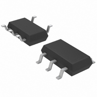
LTC1728ES5-5#TRM Linear Technology, LTC1728ES5-5#TRM Datasheet - Page 10

LTC1728ES5-5#TRM
Manufacturer Part Number
LTC1728ES5-5#TRM
Description
IC MON TRPL MCRPWR TSOT23-5
Manufacturer
Linear Technology
Type
Multi-Voltage Supervisorr
Datasheet
1.LTC1727EMS8-2.5PBF.pdf
(16 pages)
Specifications of LTC1728ES5-5#TRM
Number Of Voltages Monitored
3
Output
Open Drain or Open Collector
Reset
Active Low
Reset Timeout
140 ms Minimum
Voltage - Threshold
3.086V, 4.675V, Adj
Operating Temperature
-40°C ~ 85°C
Mounting Type
Surface Mount
Package / Case
TSOT-23-5, TSOT-5, TSOP-5
Lead Free Status / RoHS Status
Contains lead / RoHS non-compliant
Other names
LTC1728ES5-5
LTC1728ES5-5
LTC1728ES5-5
Available stocks
Company
Part Number
Manufacturer
Quantity
Price
applicaTions inForMaTion
LTC1727/LTC1728
Supply Monitoring
The LTC1727 is a low power, high accuracy triple sup-
ply monitoring circuit with three monitor outputs and a
200ms microprocessor reset output.
The LTC1728 is a low power, high accuracy triple supply
monitoring circuit with a single 200ms microprocessor
reset output.
All three V
olds for reset not to be invoked. The LTC1727/LTC1728 will
assert reset during power-up, power-down and brownout
conditions on any one or all of the V
Power Detect
The LTC1727/LTC1728 are powered from the 3.3V/3V input
pin (V
(V
highest potential. This ensures the part pulls the RST pin
low as soon as either input pin is ≥ 1V.
Power-Up
Upon power-up, either the V
can power the part. This ensures that RST will be low
when either V
as any one of the V
threshold, RST will stay a logic low. Once all of the V
inputs rise above their thresholds, an internal timer is
started and RST is released after 200ms.
RST is reasserted whenever any one of the V
drops below its predetermined threshold and remains
asserted until 200ms after all of the V
their thresholds.
On the LTC1727, each of the comparator outputs will be
low until the V
tor rises above the appropriate predetermined threshold.
The COMP3, and COMP5/COMP25 outputs are guaran-
teed to be in the correct logic state for either V
the internal bandgap reference to be valid before the
correct logic state can be output. Therefore, the COMPA
output will be held low until V
or V
10
V
CC5
CC25
CC5
/V
CC3
) or the 5V input pin (V
CC25
/V
), the 1.8V input pin (V
CC25
CC
greater than 1V. The COMPA output requires
inputs must be above predetermined thresh-
CC5
CC
is greater than 2V (typ).
/V
input that is monitored by that compara-
CC25
CC
inputs is below its predetermined
/V
CC18
CC5
CC5
or V
CCA
/V
CC18
), whichever pin has the
CC25
CC3
is above 1V and V
CC
), the 2.5V input pin
CC
reaches 1V. As long
/V
inputs.
CC18
inputs are above
or V
CC
CC3
CC3
inputs
pin,
CC3
CC
or
Power-Down
On power-down, once any of the V
its threshold, RST is held at a logic low. A logic low of
0.3V is guaranteed until both V
drop below 1V.
Glitch Immunity
The RST output of the LTC1727/LTC1728 have two forms
of glitch immunity built in. First, the input monitors require
the input voltage to transition at least 10% of the input
threshold (0.1 • V
proximately 50µs in order to force the monitor output low.
The duration of the transition must be longer for voltage
transitions of lesser magnitude (see Figure 1). Secondly,
the reset pulse width of approximately 200ms acts to
debounce the RST output ensuring that the RST output
will always be in the correct state.
The individual monitor outputs of the LTC1727 do not have
hysteresis and will track the monitor inputs relative to the
monitor’s input threshold (V
very slow moving input voltage with ripple riding on it may
cause the individual monitor outputs (COMPA, COMP25,
COMP3 and COMP5) to toggle on the ripple as the input
voltage passes the input threshold. The slow response
time of the LTC1727’s input monitors has a tendency to
integrate signals on the inputs improving their immunity
to noise and ripple.
Figure 1. Transient Duration vs Comparator Overdrive
450
400
350
300
250
200
150
100
50
0
RESET MONITOR OVERDRIVE VOLTAGE (% OF V
0.1
RTH
) below the input threshold for ap-
1
RTA
CC3
, V
10
RT25
and V
CC
, V
inputs drop below
1727/28 F01
CC5
RT3
100
CC
/V
and V
)
CC25
/V
RT5
17278fb
CC18
). A


